A little over a week ago, I launched a satirical agency website on LinkedIn - find it here at palatable.work. I made the post entirely "in character" as a deadpan announcement, the kind any of us have written or read a million times. By the end of the day, it had hundreds of reactions and a couple dozen comments. Old colleagues congratulated me. Some people texted me. I was asked in a DM about job openings (I let them down gently). I've even been told that people I don't even know have brought it up to friends, thinking it is a legit company. Even weeks later I'm getting questions about it.
While I knew the straight deadpan approach would do some of this, what I didn't expect was how weird it would feel to watch it unfold.
The site is called Palatable. It's a fake experiential agency with over twenty case studies dated in the future, a fake data platform called Lather, and a Labs division. The case studies range from uneasy to hard to watch: a real-estate developer who plants brand ambassadors as long-term residents to befriend tenants and sell to them; a children's STEM playground that secretly teaches missile guidance; a private-prison escape room where every puzzle replicates a real bureaucratic obstacle and the final puzzle has no solution. The agency refers to customers as "substrates" - beings without personal agency that only receive "brand value." The case studies are written in the same language any of us have used to describe a real campaign - clinical, corporate, patting yourself on the back. The discomfort and horror (when it lands) hits because a reader gets there on their own. I was careful to shave off as many moments of "winking" copy as I could.
Maybe (I hope) one of the more obvious problematic fake case studies where kids learn about missile guidance systems
The point wasn't to trick anyone. I even intentionally delayed the launch to be well after April Fool's because it felt like a bigger idea. Most people who 👍'd the post knew what they were looking at. Some didn't. Part of the point is that the conditions that let a fake (arguably evil) exploitative agency land as a real announcement on LinkedIn are the same conditions that let real exploitative agencies, companies or projects land as real announcements on LinkedIn. These mediums do not reward careful reading - I probably would have fallen for this post myself if I was just scrolling past. I felt that the only way I could launch something like this was to fully commit to the bit - it wouldn't have landed the same if I had posted "hey check out my dystopian experiential company lol."The voice that was used helped it blend in and made the work seem natural. I built a site to, in part, make that argument and the launch made the argument for me.
I've worked in experiential since about 2010, most of it at one agency. I've done work that I think is legitimately good and that I'm still proud of. I've done work that is fine. And then there is some work where the brief asks for something the language of the brief can't say outwardly. A campaign for a client whose business model or product was harder to stomach than the activation suggested. Invasive data capture methods, a strange target demographic, maybe exploitative of people who had no say in how the activation came to life, or a client who is actively harming the environment.
I've been in the room for real briefs on products that promised to deliver a safer alternative to smoking that were definitely just a different cigarette. I've been in a South African village that barely had a working plumbing system - I was there only to get a tech enabled vending machine to give cans of soda to villagers that were filmed for a commercial. I've executed projects for brands I would otherwise not support in public. I've been asked about all the various ways that data can be sucked out of people visiting an experience, whether they explicitly consent to it or not. I pushed back internally on some of these. Some of them I worked on anyway. That's how the structure works sometimes - individual agency and conscience is not always the lever it sometimes feels like it could be.
I've been carrying the idea for Palatable for years - maybe originally as a funny experiment or riff on "what about if this real brief was just a little more evil?". It became a viable weekend project once AI tools made the production effort match the conceptual lift. Most of the actual labor was on the case-study concepts. I had to find ideas ridiculous enough to be unmistakably as satire to a careful reader, while plausible enough that the agency voice would carry them. Finding that line is hard. I think some of the projects feel suspiciously similar to projects that already exist, even if their premise is just slightly more ridiculous.
A meaningful share of the case studies aren't about my work or my industry. They're about document corporate behavior translated into the deadpan agency voice. The Palantir case study describes a "Community Safety Lab" that aggregates resident-marked unsafe zones and sells the data to insurance and real-estate forms. The activation is invented but the data pipeline is the company's actual business. The CoreCivic case study is an escape room whose puzzles replicate the bureaucratic obstacles incarcerated people face. The obstacles are real but the the experience is what an experiential agency would be asked to build if CoreCivic decided it needed a humanizing brand moment. Raytheon, ExxonMobile, Purdue Pharma , Nestlé Waters - all similar translations. Take what the company actually does to people or the environment, render in a language that an agency uses to celebrate the work, and, voilâ, the result sometimes feels a little harder hitting than a think piece would have.
An imaginary installation for Smith and Wesson where users get a free American flag if they stick the barrel of a recently fired gun into a giant vending machine
The argument is that the language itself is the indictment. Experiential agency communication hallmarks of the casestudy format, the bulleted results with billions of impressions, the words "approach"+"challenge"+"result," and the soft euphemism about what was extracted. All of that flattens the stakes of what is being described. It's a voice designed to make commercial activity feel kind of like a civic gift, like it's not a transactional experience at the end of the day. Take three lines from one of the case studies: "100% of visitors' biometric data was retained under Section 14(b) of the terms of entry. The phrase 'my Google twin knows me better than I know myself' trended for 48 hours. Average data capture per guest: 1.2 terabytes." Read fast, that's a results section. Read slowly, it's a description of mass biometric extraction reframed as a brand moment. The sentences don't change but the register does. When you write in that clinical voice about practices the voice can't comfortably name, the gap between language and content becomes the visible thing. You aren't satirizing the practices, exactly. You're letting the language describe them in its own voice and watching what comes out.
The Yes Men have been doing a harder version of this for over 25 years. Igor Vamos, who is half of the group, was one of my professors in college. One of thier most famous stunt's was an impersonator going on the BBC as a Dow Chemical representative to apologize for the Bhopal disaster. It was a fake apology, in the language of corporate accountability, for a real catastrophe nobody had ever properly apologized for. Palatable is much softer than that. But the lineage is the same: fake corporate communication that operates in real institutional space, using the discipline's own grammar against the things the discipline does.
Someone in the comments compared the project to Giovanni Battista Piranesi's Carceri d'Invenzione, the 18th century etchings of imaginary prisons. I had to look him up. It was one of the more useful frames that anyone had shared with me about what I was trying to express.
Piranesi was trained as an architectural draftsman. The Carceri use the full vocabulary of legit architectural illustration. The precise linework, the perspective, the shading. These are all tools to render the impossible spaces of ascending and descending staircases, ropes, and pulleys whose function the viewer recognizes without being told explicitly the terrible things they can be used for. The drawings work because they look like reach architectural renderings. A clumsy version of the same thing wouldn't land, they have to be nearly indistinguishable from the real thing.
Palatable is trying to do the same trick at a much smaller scale. The case studies have to look real. The platform has to emulate what a real platform would look like. The design has to feel clean. These features couldn't slip. If I let an obvious wink into the copy, or used an obviously cartoonish brand name (the partners section, notwithstanding - Mindhonk 4evr), or described the work in a voice the industry doesn't use, the whole thing collapses into parody, which is much easier to dismiss. Parody is comfortable. The discomfort I was trying to produce with the project is the recognition that the language doesn't need to be exaggerated to describe what's happening. It only has to be used completely straight.
This all brings me back to the launch. The deadpan post worked because LinkedIn is build to reward exactly the reading habit it requires: scan, react, scroll, congratulate. This is not a failure or one particular reader, I fall for it constantly, but it is the design of the social media surface it inhabits. I'm not saying anything new when I say that the medium doesn't give people the conditions to encounter the details of the questionable case studies - it gives them the conditions to encounter an announcement.
Real exploitative campaigns benefit from the same design. The case studies that get written about real activations on real agency sites are scanned by the same people in the same way. The language flatters the reader and the work, and the reader moves on. The mechanism that let my fake launch land like a real thing for so many people is the same mechanism that lets other problematic things through. Data extraction, surveillance partnerships, targeting vulnerable demographics - can get described as community engagement and read as such.
There was one specific pattern in the comments section of the post that is worth pointing out. A small number of replies offered something like creative collaboration in the project's voice — proposed case studies, riffs on the agency's vocabulary, suggestions of brands or scenarios. People wanted to enter the world and go LARP'ing with me in a dystopian landscape. That's a sign the satirical surface has enough grit to be inhabited. It's also a sign of something less comfortable. The vocabulary fit because the role was already familiar. When on autopilot, we have been trained, by the actual conditions of contemporary commercial life, to imagine ourselves as "substrates" by default.
This isn't only about an industry doing things to other people. It's about an industry that has already done a meaningful share of these things to you. Your location data is in a database somewhere. If you've used a connected device while grieving, your grief has been modeled. Your kid's Saturday morning enrichment was probably sponsored by something. If you've ever spit in a tube to find out where your great-grandparents were from, your DNA is licensed. The case studies on Palatable are not a forecast of what experiential agencies might do in 2030 — they are mostly a translation of what has already been done, to most readers of this essay, in language that did not announce itself as harm. The deadpan register works on you because the same register has worked on you for years. Every privacy policy, every onboarding flow, every "we value your trust" email is the same vocabulary used to describe what is happening to you. You have been reading variants of this copy for a decade and clicking accept on it.
Some of what the case studies depict happens to real people who don't get to opt out of being depicted. Satire that critiques power has a cost structure where some readers may feel the work doesn't have standing to render their experience, even in fiction. I removed one case study before launch — a heritage festival concept that turned on DNA collection — because on reflection the discomfort it produced was landing on the "substrate" rather than as a corporate indictment. That removal is the kind of calibration I expect to keep doing. I'm definitely open to hearing where the rest of the work gets it wrong.
What I'm not open to is the more comfortable reading where the project is a clever provocation about a problem we all already know about. The point isn't that surveillance capitalism is bad, or that experiential marketing can go or has gone too far, or that brands are creepy sometimes. Those are all true and none of them are the core of the argument. The argument is that the language we use to describe this work is doing a meaningful share of the work itself. The register is part of how the practices remain unobjectionable to the people writing case studies about them (including, for the last fifteen-plus years, me).
If you read a case study on Palatable and recognized the room it would have been pitched in, that's the discomfort I built the site to produce. The deadpan is doing a job. So is the language any of us would have used to write the deck.
Palatable is at palatable.work (triple click the "03 Work" on the left column to see all case studies, not just a randomly generated selection)
In the spirit of this essay, it is important to me to disclose that this essay (and a large portion of the copy and content on Palatable) was drafted, structured and edited in conversation with Claude (Anthropic). The personal material, the decisions about what to keep, and the final form are mine.
This is a sort of continuation on my essays on creative tech and organizational structures, but could easily be considered its own thing.
My previous essays on this topic focused more on projects and clients and their impact on the working process. This essay discusses the broader ecosystems connected to the tools used in creative technology and experience design, tools that the industry relies on to make their work. Understanding the origins of these tools can provide valuable insights for teams working on experience design and creative tech projects.
Consider the chart below which is a sort of high level map of how I think about the “sources” of the tools used by creative technologists.
When we compare creative technology and experience design to other industries, it becomes clear that it is relatively small. How many experience design companies focus on creative technology as a core competency? How many projects to they handle annually and what are their revenues and number of employees? Despite some projects gaining significant media attention, the financial impact of creative technology remains modest compared to other sectors. Consequently, many tools used in creative tech are adapted from technologies developed for much larger industries.
Why is this important? Consider a technology like the well known depth camera, the Microsoft Kinect. The Kinect is old and essentially deprecated, but stick with me. This tool was launched in late November 2010 for the Xbox 360, a gaming console for consumers. The tech has origins from Israel's PrimeSense, and then Microsoft acquired them and moved the tech towards gaming applications. This research and development took years, and likely hundreds of millions of dollars. The original Kinect sold very well to consumers (over 8 million units. Additionally, despite the fact that the tool wasn't explicitly made for the creative technology communities, the Kinect also eventually began to get a foothold as a new sensing technology for use in interactive digital experiences. It was everywhere for a while, and we can still feel echoes of the "wave your arms at a wall of particles" projects popularized by the Kinect even today.
Now let’s consider a hypothetical case of direct impact of the creative technology community actually buying that tech.
Let’s (generously) say there are 500 companies in the US doing creative technology projects in a given year. Of those companies, maybe Kinect projects are really hot right now, and they have 3 projects each that year that all use 5 Kinect's per project (so 7500 Kinects across all companies). At $200 a pop ($400 for the Azure Kinect), that brings the grand total of Microsoft's take to something like $1.5 Million for 7500 Kinects - an optimistic estimate and a slim percentage of the total 8 million units sold. While these projects might enhance the Kinect's visibility and perceived value, $1.5 Million is insignificant compared to the consumer market and other industries. On top of that, many of these large tech companies occasionally take on these projects not as a profit-making venture, but almost more as an intensive abstract marketing effort - make a "cool" technology that can be used in a really "cool" project and attach Microsoft, Intel, Google, or Apple onto it. Consumers may not go out and buy a Realsense camera, but they might remember that Intel does "cool" stuff like that. See also, the concept of a loss leader (the Kinect 2 was reportedly sold at a loss).
So if all of these technologies aren't being made for "us", the creative technologists - who are they for? Well, there is the consumer market, there is the defense and weapons industry (remember how Hololens got a $22B contract with the military?), there is the medical industry (see Google Glass Enterprise), and a lot of other high profile and well funded industries. And I'm mostly talking about the high profile sensor technologies that a lot of us use - there is a whole other side to this in large scale AV technology like LED walls, computers, microcontrollers, etc etc. Supply and demand still mostly rules here. Below is just a partial list of tools or frameworks and either their original “funder” or what I would assume is a primary industry for that piece of tech:
Defense/Military
Depth Cameras
Infrared and Heat Sensing
Headset displays for VR and AR
GPS
Retail:
RFID/NFC
Touchscreens
"Digital Signage"
Automotive and Manufacturing
Computer vision
Various sensors (pressure, distance, etc)
Robotics
LIDAR
Entertainment (professional and consumer)
Video and display standards
Cameras, connectors and lenses
Audio equipment and standards
Displays, Projectors and LED
Medical
Heart rate sensing
*Caveat that the above points are based on observations and not detailed research
Since these technologies aren't usually designed specifically for creative technologists, the discipline must get really good at adaptive reuse. A key skill for a generalist creative tech is to be able to see through the noise of the tech landscape and make recommendations about what will and won’t work - a lighthouse in the fog. We’re sifting through other industries to find tools that enable new creative capabilities and methods of expression. However, to my point above, creative tech can be a small voice to direct change in those technologies.
The idea of adaptive reuse gets at the heart as to why working on creative technology projects can feel either exciting or truly challenging. We're often using and bolting on tools that weren't designed for the purpose we're using them for. They are often tools that were profitable enough to be produced at a high volume for a broad set of purposes (or one specific case). This is certainly nothing new to the world of creativity or working in general, but it does answer some important questions that come up over and over.
Creative Tech people may know what we want or need in a sensor, or a depth camera (higher frame rate! high resolution!), a computer, a software tool, but there may never be something that gets released that is just the right fit - so we make it work. For people reading this that might be more non-technical, I think a key takeaway is allowing for some grace when things don’t work as intended.
So with all of the above and the challenges of a broader ecosystem, how can organizations be more responsive and less reactive to tech trends? What sorts of technologies can the creative tech space have greater influence over or is the only option to try and make your own product and hope you can recoup the costs? This topic is a meaty one meant for its own separate writeup, but at a high level I think that things like creating room and curiosity for prototypes and research both inside and outside of projects can be a huge help. Having an awareness and sensitivity to the forces at play outside of the creative technology and experience design space can be a crucial step to identifying paths forward.
In part 1, we looked at what a creative technology company looks like at a sort of macro level and where a department falls within a larger company structure. Now we'll zoom in a bit to the individual department level and the various roles that fall within that specific team. In part 3, we'll look at the entire company within a project that might have multiple levels of involvement.
Creative Technology Department
Let's look at a Creative Technology department. In general, this is the team that provides creative solutions and technology oversight on projects, develops software, integrates with hardware, and performs research on new tools. It has some leadership-oriented people, and some that may prefer just working directly on project oriented problems and tasks. To start from the top, some organizations may have a Chief Technology Officer (CTO) depending on the size, typically you have a creative tech department lead that reports to them (or is one in the same). This person does things like helping to set goals for the department, setting up and championing good processes, and overseeing all projects from a high level - diving into details only when necessary. Depending on the size of the department, there may be multiple roles like a lead creative technologist or a technical director that will manage an individual project. Other department roles may be simply various levels of the title of “Creative Technologist” with a mix of individual contributors and people managers. Skill sets may vary from hardware expertise, to incredibly varied software expertise in everything from TouchDesigner, game engines, javascript, backend systems, and more.
Due to cost, many companies have to be very strategic about the skill sets needed (generalists versus niche platforms) and seniority levels they bring in. A company may lean towards more of a “We can do it all” or ”Diner menu” mentality that can tip them towards needing more creative tech generalists who have a “T shaped” skill set. These T-shaped generalists might have a wide (and shallow) range of knowledge about all things creative tech and one or two “deep” specialized skills. Other companies may choose to specialize in a particular aspect of Creative Technology and may say: “We only do augmented reality for the mobile web” which means that they can focus their hiring efforts considerably, but they also have the tradeoff of having a potentially narrower client base that only wants mobile web AR. Both approaches are certainly valid and have tradeoffs between casting a wide net for client projects and level of executional skill.
With all that in mind, below is a diagram of a hypothetical creative technology department structure for a small company with a generalist focus.
To describe the diagram a bit more - The Director level typically handles things like department goals and direction, hiring, planning, staffing projects, career advancement, setting individual goals, and helping to guide processes. Lead Creative Technologists or Technical Directors are a bit more on projects and may split their time between team and project management and some active development. The Creative technologists and other members may work more directly on projects but will still have a bit of creative and architectural input to how things are done. Next we'll take a look at how this same setup might be split up across active projects.
Creative Technology Department Structure on Projects
Moving past a department structure, there is the consideration of how that same structure plays out when actively working across different projects in production. Here is where it is critical to balance individual skill sets, budget, time, interest, seniority level, and other elements across the right projects. You may have several projects running at once - maybe several small projects with only a small creative tech component, and maybe one large project that has multiple layers of software and hardware that is taking up most of the team’s resources. Balancing teams and timing across the constantly shifting sands of project-based work will take a large chunk of time for Creative Tech department leads.
The scale of the project may necessitate the need for a separation of a hardware lead and a software lead. While there is a ton of crossover on hardware/software, there can be a ton of time involved in dealing with the specifics of the hardware and integration with the built environment. The creative tech lead will work with the department lead to identify things like project scope, milestones, and overall project health. Also depending on the scale of the project, the software lead may be developing significant parts of the project, or just overseeing the process and jumping in on specific elements. Next up, the creative tech lead oversees the general or specialized developers with the right set of skills for the project - and these might be a mix of full-time employees, freelance individual contractors, or a small vendor with several developers working together.
Below is a diagram that gives a hypothetical view of how a creative technology department might split resources across several different project types - like a consumer facing AR app, a sound-based experiential project, and a permanent installation involving web technologies.
Questions for department leads to consider at this level:
How does this scale?
What does this kind of structure look like at 5 employees and 2 projects versus 50 employees and 10 projects? What about 200+?
How many people do you need per project?
How do you balance the capital “C” creative members with the capital “T” technologist members of the team? Some might need more technical mentorship, and some may want to be more involved on pitch and concept work.
Can a technical project lead do heavy software development or get too “in the weeds” and still be an effective lead?
My answer: I think it is difficult for a lead of a team to get too involved in the weeds of development and deployment. The tradeoffs often are that their technical skills can often lose a bit of sharpness if they aren’t actively developing something, or that the larger picture for the team can get lost if they are too deep in details on a particular project.
Is there a better way to structure these project teams? The approach above feels like a "standard US agency" based approach, but there are many others.
How does it change for a short term versus long term project?
Who are your next 3 most needed hires and what are their skill sets?
How many specialized skill sets can you reasonably have "in-house" versus needing to hire specialized freelancers?
What is your company’s “specialization”? Is it easier to focus on your core competencies and then either find trusted partners or hire freelancers each time?
How do you make space for Research and Development projects (that don’t necessarily generate revenue in a clear way) while also keeping up with paid client work?
What is the challenge or value of productizing some of your offerings?
How do you split off time to template out or productize certain repeatable elements of your creative technology work?
How many times would something need to be used repeatedly to be worth the investment in productizing?
Do the rest of the teams feel aligned to "re-sell" the product being built or considered or is it mostly a tech team initiative (for example - a small communication or monitoring utility vs a larger complete app/SaaS tool)?
How do you onboard new hires into this structure and explain the working process?
Similarly, how do you onboard new freelancers and vendors to your process and how do you vet these new team members?
How do you balance the need for consistent process and the need for flexibility across vastly different projects? Too much rigidity to process can make it difficult to work with other teams.
What is your team's own "API"? -> How do you balance your team's internal process (for example: how do code reviews work, when do we push things live) vs external process (for example, how do you interface and update the creative team and production team when challenges arise?)
Are people burning out or does their workload feel manageable?
Are people getting burnt out from working on the same kinds of projects all the time, or too many different ones?
How many projects can one person work on simultaneously?
My personal answer for a developer: 2 in production - maximum, and maybe 1 in pre-production/concept creation. Context switching is expensive.
Are people being mentored appropriately?
Is there a clear path for career growth from one level to the next? How do you make this explicit to the team?
If flat hierarchies are preferred, who ultimately makes tough decisions?
How do you build multiple coherent paths for people who want to be more of a manager, or more of a creative, or more of an engineer - and are those paths necessarily divergent?
In Part 3, we'll cover how these departmental and company structures fit into an overall project structure that may involve other vendors, clients and other entities. Thanks for reading!
Experience Design and Creative Technology projects and companies can be an exhilarating mess sometimes.
This is not a problem unique to any one company - the “behind the scenes” processes of bringing incredible experience design work to life often feels frustrating to the people that do the work in companies large and small. Many projects have big creative visions, tight timelines, tighter budgets, move quickly, have vaguely defined boundaries, and are often working with cutting edge technology that inherently doesn’t have a clear path of efficiently working with it. No judgment - it is a really hard problem, and we could all use a bit of perspective sometimes.
In this multi-part series, I'm going to explore and reflect on different detail levels of the various organizational structures I've observed while working on professional creative technology and experience design projects. I believe that for everyone to do better work, Creative Technology needs more leaders thinking broadly and organizationally, not just on an executional “just make the thing” project level. These essays will be looking at this topic primarily from my personal perspective of working in creative technology in an advertising and experience design space, but I think there are some valuable insights for anyone working in the experience design field - producers, creatives, strategists, etc.
To be up front - I have struggled with the “who is the audience” for this piece, but wanted to finally share it out regardless. My hope is that students and newcomers can get a peek inside the industry and see where they might want to land, and department leads can get some perspective on how different companies approach the issue of process and structure, project managers can better understand the nuances of creative tech resourcing (i.e. freelancers vs staff, varied irregular skill sets). I think that by considering the role that you and creative technology play within your organization, you can start to think more operationally about how to improve your process and work more effectively with other teams and clients.
Overview of Upcoming Essay parts:
Interrogating the systems involved at multiple levels of detail can (hopefully) help us improve the ways that we work together, but this multi-level view can also give us a way to grapple with some of the real challenges of this kind of work.
In Part 1 (this part), I’ll actually start at the company level to provide some broader context first.
In Part 2, I’ll be exploring the micro level of just a hypothetical Creative Technology department within a company
Part 3 zooms out to the project level to bring it all together. We’ll look at the company within a project and compare direct-to-client versus an agency experience. It will make sense in the end, I promise.
For Part 4, I'll cover my perspective of how other industries "feed" the creative technology space and ecosystem - i.e. where do new technologies originate from and how do they become common tools for use in various creative technology applications?
In Part 5 (also at a later date), we'll actually turn inward a bit and cover some more philosophical points about how someone's personal (or a company’s) hierarchy of values will influence the work that is being created.
I think the value of looking at this field from these different levels is that it can help give some perspective from the day to day noise, and allow us to think about how to bring more meaning to what we do and how we collaborate.
Preamble: What do you mean by Creative Technology?
“Creative Technologist” is still a job title that many find hard to describe. The title ends up meaning very different things at different companies, and it can be hard to pin down what creative technologists could and should be doing within an organization.
For newcomers to creative technology, when I'm (personally) speaking about creative technology I mean projects that involve a wide range of things like: data-driven generative visuals on large LED walls, cameras and AI, buzzy buzzword technology activations, tried and true thoughtful and artful tech, interactive installations with sensors and robots, experiences that incorporate technology in creative ways, etc. There is a wide spectrum of work from pre-rendered assets to generative real time systems, and physical interactions to web-based interactions. The projects come to life at events, online, as mobile apps, as physical installations at museums, corporate lobbies, public spaces, and many other places.
When attempting to explain to my parents or other folks what I do as a Creative Technologist, I recently find myself reaching for this explanation:
I am an artist, and just like a painter’s medium is the full range of paint types and canvases, my medium is technology itself. I am considering the full offerings of hardware and software - their strengths, their weaknesses, their user experience, their reliability and many other factors. I look at the strategy, the concept, the timeline, the team, the landscape of technology and make informed choices about what technologies could be utilized to make the most enjoyable and thoughtful experience for a user. I also make and implement those choices to bring an actual project to life. In my personal experience, so much of what I do is about the theater of experience and picking and choosing technologies to bring that vision to life in thoughtful ways that honor the person experiencing something and the team creating it. Keeping things simple and letting the technology support the concept are some guiding principles.
Let’s first take a look at the broad range of organizations that may have creative technology as part of their offering. There can be a range of things to consider here, like degree of freedom in the work and whether you have clients or no clients at all. Depending on the size and "flavor" of your given organization's focus, your overall structure may be radically different. First - let's consider the range of organizations that creative technologists often find themselves in:
Solo Artist or Freelance Creative Technologist
Doing your own work or contracting with a company. Nobody can tie you down.
Artist's Studio
Working for a big name artist or a person who has a particular way of working
Startup
Maybe an experience design company, or maybe more product focused (or both)
Agency
Advertising or otherwise. This is a fairly fluid category where the ratio of “idea making” to “real making” can vary wildly within each agency. Some agencies just make ideas and hire talented partners to help bring them to life, and some are full-service and do everything from strategy, concept to execution.
Fine line between what you would consider a studio versus an agency - perhaps these do more work for cultural institutions
Production Company
Handling many aspects of a complete production, but often are closer to execution of the idea than the original concept creation of that idea.
Brand
Brands sometimes have their own "innovation labs" that do creative tech R&D
Product
Some startups or products start in a sort of “Design Innovation” stage and need creative technology to bring it to life
Content Studio
Primarily concerned with making digital assets like motion graphics, but many of these are beginning to bleed into experience and have their own creative technology departments
Live Visuals and technology for Touring Music Acts/Theater Productions
Primarily things that fall outside of the scope of typical lighting/sound tech
Many others...
Personally, I primarily have experience with the agency model, but most companies have somewhat similar structures and types of departments. The differences seem to mostly be in labels, and the overall scale of the other departments. There are also often echoes of whether a company started off as something else and then eventually integrated or bolted on a creative technology department. For example, a company that was originally a motion graphics company may have a lot more motion graphics artists, art directors, and creatives than a company that was originally more of an architecture firm that may not have as much content creation as a core offering.
Starting from the top, a CEO/Founder or a few founders will typically be the key decision makers. Next up, an Operations and/or Production department handles everything that makes the business run smoothly - financials, project management, process, hiring, contracts and legal, etc. The Creative team handles everything from concepts to copywriting, art direction, and asset creation. The Technology team may be a mix of engineers and more "Creative Technologists." There is also often a Business Development team that helps to bring in new work and grow existing relationships. Strategy is a mixed bag of whether it exists as its own discipline at different agencies depending on the size - some creatives are expected to think like strategists, but it really is its own speciality that works to clearly connect creative work to business goals.
There are lots of different ways to carve up these departments and their purpose, and there are certainly other departments that could be added to or divided in different ways - architectural, PR, design, UX, systems, etc. The important thing to note here is that each department typically has their own goals and levels of success measurement that (hopefully) ladder up to some larger company goals and values. Creative Technology departments don't succeed all on their own, they need some mix of help from many other specialties.
Also - as you can see above, there are some big hypothetical differences when scaling up from just a few people to a much larger team. Some companies may have a totally lopsided structure that indexes much more in one area and farms the rest out to other companies and trusted partners, etc. and the diagrams above are really meant more to illustrate potential structures at play.
Finally, I'll end part 1 on some provocations and questions that I feel come up a lot at this sort of level. While I could provide my own answers and insights for each of these, I feel like it would make this exercise overly long - but perhaps one day I'll do a breakout of my own thoughts on each of these.
Questions for Department Leads to consider at the Company level:
How can the Creative Technology team work most effectively with other departments?
Can budget and timing estimates get more accurate for the production team?
Can workflows and technical hurdles be more clearly explained to the creative teams so that there are less misunderstandings as the project starts to take shape?
Can concept prototypes be made more quickly so the business development team can sell through an idea to a client?
Is it worth it to do a risk assessment of a project and consider all unknowns and points of failure ahead of starting so that all teams are on the same page about where things may need to pivot later on?
How can other departments work most effectively with the creative technology team?
What boundaries are necessary around a typical development cycle and result in the “best” product?
If a waterfall development method isn't yielding appropriate results, how can all departments adjust their approach to allow more time for testing and iteration?
How can other teams work more collaboratively to understand the challenges facing certain technology solutions and work together to find an ideal solution?
Are departments more effective when they "stay in their lane" and are siloed, or when they are cross-functional and interdisciplinary? What is the line of crossover?
What is the role of research and development work for the creative tech team and how should that work be disseminated amongst the other teams?
Why don't companies more openly share things like org charts and the way they work (either internally or externally)? Is it a sign of a secret sauce, a lack of structure, or just that there may be limited value to others?
Is the creative tech team a "core" offering for the company that the rest of the company is truly investing in, or does it seem like more of a curiosity with a short shelf life for the company?
What parts of producing a creative technology project are unique? What additional skills would you want a project manager or producer to have if they are coming to join the team from an events background/software background/content production background?
How can you effectively add in a "typical" software development cycle approach to a shop/company/team that is used to working in a different way? Does the software process need to adjust more than the rest? Where can everyone compromise?
In part 2, we will cover more of the details around an actual creative technology department within a company. And in Part 3 we'll look at both that department and the company as a whole within the larger ecosystem of a company. Links will update here in the coming weeks.
Acknowledgements
I've actually been sitting on this set of essays for a little over 2 years, and I've been sharing it privately over the course of those few years and soliciting encouragement and feedback. I've gotten a ton of useful notes from a number of peers and friends (some of whom may not even remember helping out!) that I wanted to acknowledge sooner than later since it may take some time to publish the last few parts.
The PDF formatting is a little ugly due to the export process from a pile of markdown files, but it is at least one single document that could potentially be printed.
2023 or 2024 updates will be coming soon after! Please send me any suggestions you may have for additional things to add!
Creative technology is a topic that that I've been focused on for years. I've been writing some deep dive pieces on various topics like display technology, installation maintenance, and projectors, but there has always felt like more to cover. There has always been a feeling of wanting to tackle something even larger, like a book, but articulating the reasoning for going after something larger eventually feels like a good first step.
Creative technology is a discipline that has been evolving from other fields for a long time, but every year it feels like it is becoming more and more of an established path in academia and professional circles. However, I feel that there is a still a lack of clarity about what this field is and what it encompasses. Creative Technology is a discipline that is exceedingly broad, and most people and organizations operate within a niche of the overall field. Developing a common language and classification system for creative technology and a set of grammars to work with can really allow us to make better "music" together and help educate newcomers in a broad, but quickly digestible way. Having a taxonomy is also a useful way to have a historical mile marker for the state of the discipline in 2022, and maybe have a way to see what has evolved and changed 5 or 10 years from now.
To continue this conversation, I'm supplying a visual map of various tools and concepts utilized in the creative technology space. I originally made a version of this back in 2018, but have been updating it since then. As a caveat, the diagram is flawed as a hierarchical tree diagram and could really use an alternate method of visualization because of how complex and interconnected many topics are. To help with expanding this idea in the future, I'm also releasing a JSON file on Github that represents the exact same structure in my (originally) manually made visual map. The hope is that this file can be used to create alternative visualizations of the same data on an interactive site, and perhaps eventually be translated to other languages. One thing to keep in mind is that this classification system is primarily from my narrow perspective, and most of the map represents my personal awareness of certain areas.
A large part of my background is in music, and that knowledge base often feels like it influences this approach I'm trying to articulate. As an oversimplification, music theory is a set of mathematical and conceptual systems that facilitate the creation of music between people. It is keys, modes, notation, rules of harmony, chords, instrumentation and many other ways of describing everything from silence to noise. You don't need to know music theory to make beautiful music, but formalizing the systems behind music has unlocked a lot of different areas of potential. I would argue that the primary function of music theory is for communication - for example, allowing people to play in the same key when improvising, but also to talk to the past and read and play some sheet music composed hundreds of years ago. Music theory gives beginners a place to explore and understand in a known, quantifiable space with seasoned professionals. It is a system that enables creativity.
Aside from looking at the known - another huge function of music theory is that it gives people a language and a set of tools to also explore the unknown in a systematic way. Learn the rules so you can break them in a meaningful way. The constraints should feel more freeing than limiting. Like Schoenberg's twelve tone row, people may look at the idea of standard musical keys, throw that out entirely, but keep the other formalized elements of rhythm and notation to develop something new. They can look at the very concept of tonality and find a space between that and noise that somehow still speaks to us in a deep, ineffable way. It is possible we would have stumbled on some of these musical discoveries by accident (and some we absolutely did, don't get me wrong), but I would argue that forging into the auditory wilderness for exciting discoveries was greatly helped by a collective system that helped people understand why you went there and also how to get there themselves. New edges are found all the time that continue to push music into exciting spaces year after year.
Instruments could have remained a group of individual noise makers that worked on their own (and probably worked a bit like that for a while), but as soon as people tried to get one to talk to the other in a pleasant way, the effect snowballed into some of the most incredible forms of human expression and art the world has ever seen. Strings, woodwinds, brass, percussion and everything else - composers know all the options and what their strengths and weaknesses are.
All of the above is to say: developing taxonomies and defining systems are critical elements of getting to better art. People can have a common language, a way to describe what works and what doesn't. They can define trajectories over past decades and look at where things are going in the future. Taking a big picture view of the creative technology space can help us see the forest for the trees as well.
So what kinds of systems and taxonomies am I talking about, specifically?
As I mentioned, I've written things like guides to: cameras, projectors, alternative displays - all with a focus geared toward making interactive installations. I did this because I couldn't find anything comprehensive at the time. When coming up with creative solutions for creative technology projects, it sometimes felt like I was starting an undefined research project every time. Most projects had a need of an input method, a processing method, and a display of some sort for feedback to a user. If all you know of displays are LCD monitors and touchscreens, that might be all you might think of for output. If all you know are webcams for interaction, that's all you'll ever use.
Of course there is other stuff out there, but not everyone has the time or interest to do the research - and frankly, they shouldn't have to. Research into this stuff is important, and can help with learning and finding solutions quite a bit. However, the process of deep thoughtful research can often feel divorced from the process of free flowing creativity. Having a shorthand reference of tools, approaches, and rules can capture sparks of creativity that wouldn't have been there otherwise. Imagine if musicians had to agree on a new tuning system or had to make their own instruments every time they wanted to get together and play.
Defining creative technology systems is also a critical task for inviting newcomers.
The systems are here for you, come play music with us.
The thoughtful creativity you bring to the table is considerably more important than knowing how to wield all levels of a complex technology stack. Personally, open source software tools taught me so much about this. A small group of individuals working on tools like Processing, Openframeworks, or Cinder abstracted the approach of difficult low level programming problems and saved literal years of development for everyone who used those tools after them. Going through and learning the end-to-end pipeline for drawing a pixel on screen from scratch is certainly a worthwhile effort for some, but others just want to draw a circle on a screen and make some art. I'm speaking about more than just open source software here, though. This is about defining some of the other layers to the puzzle of finding solutions with creative technology - like hardware, displays, sensors, testing, etc.
On the professional and industry side of things (at least in the West), there is some protectiveness to sharing some of this knowledge that ultimately impedes creativity and innovation. Individuals at companies spend a lot of time solving and researching the same problems over and over, typically low hanging fruit problems that have already been solved by other companies that chose not to or didn't think to the share the results. Content management systems, people tracking with cameras, stretching images across multiple displays, uptime monitoring, etc. - most could be solved once and distributed. Available technologies and solutions are largely the same for everyone in companies that utilize creative technology, but their process and creative approach for how they used that technology should really be what defines the company's value. There are absolutely companies that share a lot of tools and findings, but hey - there should always be more.
To close, my taxonomy visual is not meant to be definitive or even remotely correct, just presented as a conversation starter. With every new branch I added, I questioned the utility of what I was adding and thought about how other people would classify things in completely different ways. I also think its only one piece in the puzzle towards creating a common language and way of working. Music theory is not just a list of instruments, but a whole language of collaborative expression. I would love to join with others on a way to keep this open and expansive - I think setting up a GitHub pages link with a graph driven the taxonomy JSON would be a great next step.
Thank you for reading. I'll close by sharing some links to some other great resources that help to cover a wide range of creative technology topics. Please leave any comments below, or send me suggestions (or a pull request) about what to add to the map.
I think that the new Apple AirTag is a deceptively revolutionary piece of tech, especially for the experience design and creative technology world. Here are 30 creative ways they could be used.
You may have heard - Fake Love, the experiential agency of The New York Times, is closing down. As part of moving on to the next chapter, I’d like to talk a little bit about what Fake Love has meant to me over the last decade.
This article was originally posted on Medium in 2016, but I have since migrated it back to my personal site to keep it updated. This version will be kept as a sort of historical snapshot of 2016 with some slight updates in 2018, but I will provide an update/changelog in another post and link it here when it's done.
An artist has a large range of ways they can display their work. Cave walls gave way to canvas and paper as ways to create portals into another human’s imagination. Stained glass windows were early versions of combining light and imagery. Electronic displays are our next continuation of this same concept.
A photon is emitted; it travels until it reflects off of or passes through a medium. That photon then passes into your eyeball and excites some specialized cells — when enough of these cells are excited, your brain turns these into what you perceive as an image.
However, standard computer monitors, LED video walls and projection screens offer only a small glimpse of the range of possible visual illusions. Any traditional display can be augmented or used in an unusual way. New displays and technologies are still being actively developed and researched. Some content is suited precisely to being shown on a standard display, like a webpage. Other content is better suited to a space that exists beyond the screen’s surface and enables a sort of suspension of disbelief that this thing is really there. We continue to find new ways to construct the image of new destinations within the eye.
Knowing the range and limits of these different displays is similar to a painter really understanding their choice of paint and surfaces. Spray paint behaves very differently than oil, watercolor or ink. Drying times, color depth, texture, reflectivity, ability to blend colors — these are just some of the characteristics the painter must consider when choosing a medium for their new work. The textures of canvas, concrete, metal also impart a particular surface aesthetic. The same considerations can be a part of a digital artist’s practice when they work with displays.
Additionally, musicians use what is called extended technique to explore the absolute limits of what sounds are possible with their instrument. Mastering an instrument with classical training is one dimension. Extended techniques demonstrate a deep understanding of how these devices function and respond to human input. Things that may sound like mistakes at first can be honed into highly expressive new tools. Violins can be made to sound like cellos with the right bowing method. Video and film artists like Nam June Paik and the Vasulka’s have been exploring extended techniques for displaying video since their inception — but it is important to continue this tradition. There is still much to discover.
Nam June Paik’s Wobbulator
The purpose of this article is to collect and consolidate a list of these alternative methods of working with displays, light and optics. This will by no means be an exhaustive list of the possibilities available — depending on how you categorize, there could be dozens or hundreds of ways. There are historical mainstays, oddball one-offs, expensive failures and techniques that are only beginning to come into their own.
This document will hopefully serve as a reference for artists who are curious about pushing their content outside of a standard screen. Some implementations are incredibly practical and achievable on small budgets, and some require very specialized patented hardware that only exists in a lab somewhere. It is important not to get bogged down in the specifics of the technology, but to recognize that these all exist on a spectrum of information transference that employ light, medium, and brain. By keeping things in these simple terms, you are free to mix, match and re-appropriate to tell new stories.
It is worth discussing a few notes about the standard displays that most digital artists use. Many of the other things discussed in this article aren’t standalone technologies, but rather techniques that modify or adapt pre-existing technologies into new applications. Each of these technologies could fill several books, so we’ll just touch on some relevant bits.
These can be a range of different technologies. Cathode Ray Tubes or CRT displays were common up until about 2005 but are difficult to find these days — they do have a lot of unique properties (not necessarily good ones..) that aren’t available in many standard modern displays. Right now, the most common display is the Liquid Crystal Display or LCD and it is in most laptop screens, desktop monitors, commercial TV’s and so on. LCD’s have a backlight, a rear polarizer, a glass layer with electrodes and liquid crystals that react to electrical changes, and a front polarizer. Each pixel has a set of 3 sub pixels with red green and blue color filters that can be combined at different levels to recreate their millions of colors.
Things like Quantum Dots are on the horizon to further improve LCD’s color reproduction and accuracy by allowing more precise tuning of light wavelengths. Plasma displays were contender for LCD for a while, but they have become less popular. Pixels in plasma displays are individually lit which result in a deeper contrast compared to LCD’s. Organic Light Emitting Diode displays or OLED displays operate in a similar principal to Plasma and have started to become more and more common. OLED has a lot of interesting properties since it can be made smaller and thinner than LCD or Plasma, this means that flexible displays and transparent displays are a much more viable option with OLED. OLED is still quite expensive in comparison to LCD’s at the moment, but this will change as the market shifts. MicroLED is another technology that works in a similar fashion but is still very new.
Standard monitors are affordable for most applications, are high resolution which makes them ideal for applications when the view is standing up close, have a decent color and dynamic contrast range, accept a variety of inputs, and are long lasting. Their brightness is suitable for primarily indoor applications. Brightness of these is generally measured in nits or candela/sq meter — most laptop screens are around 300nits at maximum. For outdoor applications, you have to source specially made outdoor monitors that are weatherproof, can withstand a variety of temperature fluctuation, and have a considerably higher brightness rating — some available ones can do 1500 nits or more which would be almost painful to look at up close in an indoor setting.
Of course, these displays have their limitations. They are only viable up to a certain size for a single unit. Most of the largest max out at 120in or 305cm of diagonal image. Past this, they must be tiled together to form a larger video wall, and there are inevitable lines or bezels between adjacent units. Even those larger video walls start to reach a limitation at a certain point where Projectors or LED video walls are a more economical choice. The color and dynamic range of these monitors appears to be decent, but it is actually not as good as you might expect — we are missing out on a whole range of visible colors. Most standard displays are also locked at 60hz refresh rate (the speed that the screen is redrawn every second) which is perfectly fine for most applications like movie watching, but things like gaming monitors have started jumping to 144hz or more. Even though our brain’s visual refresh rate is about 60hz (a huge oversimplification), there are some intriguing things that can be done with a higher refresh rate. Imagine scrolling this page up and down and having it look as natural as a piece of paper moving up and down instead of the commonly jittery experience. There are also researchers looking into using high frame rate or high temporal resolution displays to do things like turning normal displays into higher resolution displays — here is an incredible survey of a range of options with computationally augmented displays. Consumer displays are also typically two dimensional and flat, even if displaying 3D content with glasses or another method.
I have covered projectors in depth in another article so I won’t go into detail with them here. It is important to remember that they are not much more than a fancy implementation of a light source, an imaging element and a lens. They are best for darker environments, but they tend to be the most economical choice for large scale imagery. It is also easier to blend multiple projectors together more seamlessly.
LED Video Walls are another common option for displaying digital art on a large scale (also called LED Displays — not to be confused with LED Monitors where the light source is simply the LED backlight). These are usually comprised of individual tiles that are linked together and driven by a special display driver box that addresses the tiles from a standard monitor input. The tiles are generally either single all-in-one RGB LED’s or larger individual R,G and B LED’s that are placed close together. The primary spec of an LED wall is its pixel pitch, measured in millimeters. If you are viewing a wall close up, you want a low pixel pitch — some of the lowest available are around 1.6mm. Larger pixel pitch like 16mm to 20mm is perfectly acceptable if your viewer is really far away from the screen because their eye won’t be able to discern individual pixels as easily. LED walls are also one of the only display types that can be viewable in direct sunlight. Some of them are 3000nits or more of brightness, which explains why they are the display of choice in places like Times Square.
They have a wide variety of models and applications. Some are used as jumbotrons in stadiums, as high end storefront signage, or are used as sculptural stage elements. Some move towards the spectrum of lighting elements and are extremely high pixel pitch. These large pixel pitch tiles can be used almost as “transparent” elements because when the audience is far away, they are able to see through the frame — as in this video wall. Stage lighting examples are the LightSlice, Vanish, and the Saber. Some manufacturers also provide custom LED tile work and can do more unusual shapes like spheres or triangles.
The primary drawback of LED walls is cost, although the prices have been dropping rapidly in the past few years as these become more commonplace. Finding price points for certain elements isn’t usually publicly available but it can cost around $2000 for an individual tile and the driver box can be $5000–10,000. Most LED walls are typically rentals due to the large cost of purchasing them. They do last a long time in the case of purchasing, but even a modest sized wall at a high resolution can run into the hundreds of thousands of dollars very quickly. The cost of installation (for rental or permanent) can also be an additional hurdle since you typically need an experienced technician to set them up and get the pixel mapping established. They also have a particular aesthetic that is suited to viewing from far away. Up close they can be uncomfortably bright, and their pixels can be a distraction. Some stage designers will overlay a black or dark grey rear projection material or even acrylic overtop of the LED’s to soften them and provide a more diffuse look.
A Brief Note on Holograms
To get this out of the way early, It should be mentioned that none of the displays mentioned below are in line with the definition of a hologram. A hologram is closer to a photographic medium as it captures an imprint of the light waves that bounce off an object. Most of the media headlines these days with the word “hologram” are typically talking about simple optical tricks or AR. Holograms have taken on a cultural meaning that differs from the scientific definition, similar to the cultural rebranding of “synesthesia” or “literally.” This article by Oliver Reylos has a concise summary of what is considered holographic and what isn’t. In his words:
When viewing close-by objects, there are six major depth cues that help us perceive three dimensions:
Binocular parallax / stereopsis: left and right eyes see different views of the same objects
Monocular (motion) parallax: objects shift depending on how far away they are when head is moved
Convergence: eyes cross when focusing on close objects
Accommodation: eyes’ lenses change focus depending on objects’ distances
Almost all of the displays or techniques in this article have some holographic properties like parallax or multiple viewing angles, but are primarily in a class of their own. Would you call an oil painting a sculpture?
Pepper’s Ghost is a classic illusion — it has been around for over a century and is still making headlines. 99% of the time, when you see a headline with the word “hologram” it is talking about Pepper’s ghost.
Historically, the effect comes out of Phantasmagoria, a fascinating tradition of theater illusions that were developed in the 18th and 19th centuries that frightened audiences with never before seen images of spirits and floating otherworldly beings. The Magic Lantern is another one of these early theater effects and it is one of the earliest forms of the projector. The name Pepper’s Ghost comes from John Henry Pepper who popularized the effect in the mid-1800’s with his friend Henry Dircks (who arguably developed it before Pepper). However, the illusion was first described in the 1600’s by an Italian scholar named Giambattista della Porta in his book Natural Magic:
Wherefore to describe the matter, let there be a chamber wherein no other light comes, unless by the door or window where the spectator looks in. Let the whole window or part of it be of glass, as we use to do to keep out the cold. But let one part be polished, that there may be a looking glass on both sides, whence the spectator must look in. For the rest do nothing. Let pictures be set over against this window, marble statues, and suchlike. For what is without will seem to be within, and what is behind the spectators back, he will think to be in the middle of the house, as far from the glass inward, as they stand from it outwardly, and so clearly and certainly, that he will think he sees nothing but truth. But lest the skill should be known, let the part be made so where the ornament is, that the spectator may not see it, as above his head, that a pavement may come between above his head. And if an ingenious man do this, it is impossible that he should suppose that he is deceived.
Pepper’s ghost is very easy to implement. The simplest version involves a transparent reflecting surface (a sheet of glass, plastic, or a half silvered mirror), and an image source (a monitor, projection screen, or a lit source). There are two versions of this effect that are commonly used — the classic one from the 19th century typically involves two separate physical spaces and specialized lighting. The modern version of Pepper’s ghost involves a digital screen (monitor, or projected image) and a half silvered mirror or specialized film designed to be invisible to the viewer. This version is also used for teleprompters where the camera lens is positioned behind the mirror facing the speaker. Both are essentially the same in principal.
Glass mirrors are the most accessible way to achieve this effect (it can even be done with reflective plastic and a smart phone), but at a certain point it becomes difficult to scale the glass to be large enough. For stage productions, there is specialized plastic film that can be employed to reflect much larger surfaces. Musion is the primary company that comes up while searching, and another is Arena 3D. It is worth noting that Musion claims a patent on a version of this 100+ year old technology and has hit “imitations” with lawsuits in the past. It is also easy to source your own film from 3M or other sources in Asia — another version of the film is manufactured by DuPont.
Image of reflective foil setup for stage production — Source
Carefully controlled lighting is essential for this effect to look its best. The source of the image must be bright in comparison to the surroundings behind the transparent surface. The observer should also be in a very dark space so their own reflection doesn’t show up in the mirror. It is also helpful to have something slightly visible behind the transparent surface so that your floating image has something to float overtop of and give the viewer the parallax depth cue. The effect can be striking if combined with props behind the mirror — like a person sitting on a chair or animations that swirl around an object. However, there are limitations to this depth effect.
Peppers ghost is still very much a 2D effect and does not present an image in three dimensions. It is just a mirror reflecting another flat plane. Parallax between the reflected image and the background is what gives our eyes the illusion of the content floating in mid air. A false sense of 3D can be achieved depending on your source and how the reflecting surfaces are arranged. There are some implementations of the effect that put 4 mirrors in a pyramid shape under a monitor (some have marketed themselves as holograms — sparkingcontroversy). By having the monitor display a different image for each mirror, the observer gets more of a 3D view as they walk around — even if it is just 4 discrete viewing angles. Head or eye tracking would have to be employed to make the effect a little more convincing, but then it would only work for one observer at a time. As it usually functions, the effect may look best from one vantage point, especially if you are trying to align it with an object behind the surface. This misalignment can be minimized by having your observer be further back so when they move their head, the parallax isn’t as great as if they are right in front of the screen.
Projecting on semi-transparent materials is essentially a variation on the Pepper’s ghost illusion. It is also an effect that has been used in theater for a long time. In contrast to Pepper’s ghost, this technique uses a transparent material to catch (not just reflect) the light from a projector. The viewer can still see through the material, but the projected light is scattered and appears to be transmitted from the material. Viewers can still see through the material allowing for a depth effect from parallax, but the illusion is still flat and two dimensional.
The implementation of this technique is one of the cheapest and most accessible on this list. You will need a semi transparent material and some means of projecting an image. The material you use depends on the scale or size of the end result and the type of effect you are going for. You also must consider whether you want to use front or rear projection. Rear projection (with the viewer facing the projector lens) will produce a noticeably brighter hotspot depending on the material used and where the projector is, and front projection means the image will spill behind the surface a little bit which may result in some doubling.
As far as materials to use, on a small installation you may be able to get away with just a piece of fabric like tulle or netting — things like bridal veil material. White fabric will catch and transmit light the best, but sometimes black can still work and give you a similar effect with the fabric appearing more “invisible.”
If you are trying to have an image appear on a storefront window or piece of glass, you will need a specially engineered film that is nice and transparent but still collects a lot of light from your projector. The proper film for glass can be very expensive for large pieces, so keep that in mind. One source has it at almost $1200 for a piece that is 2.2m by 1.2m. Here are some possible vendors for this kind of film: [One] [Two]. You can get away with cheaper materials, of course, but the effect may be very different. Cheaper or DIY material may be either more opaque (yielding a brighter image but less transparency) or too transparent (yielding a faint image). Projecting on glass will certainly show something if there is significant dust on it, but the effect will be very dim.
To achieve much larger images for theater or stage, fabric is the most economical choice for a scrim. You can get very large seamless swaths of fabric for the purposes of stage projection. Some fabric will have larger holes in its netting which will make it more transparent but will also cause your projected image to be less bright as well, in addition to dropping the sharpness and fidelity of the image. Here is a great resourcefor more info on stage scrim projection materials, including silvered fabric. You can also layer these materials to get several planes since the light is passing through. The cone of light from the projector will cause the image to be larger or smaller on each depth layer depending on whether you are projecting from the front or the back. You can also only go so far with layering before your light runs out or just gets out of focus.
Similar to the requirements for Pepper’s Ghost, this technique requires very controlled lighting. You will need to balance the ambient light that is hitting your fabric so you can preserve the illusion of a floating image — otherwise it can just look like a standard projection screen that you can see through. Contrast is key here. It also helps to have the space behind the image not be completely dark to give the image more dimension. If the viewer can see behind the image then they get the layered effect and the sense of parallax that helps it appear more 3D even if it is still just 2D.
Content that works best on any of the semi-transparent materials tends to be imagery that does not fill the entire projected rectangle. The optimal approach is to have your content sit on a field of black, so that that it appears to have no bounds. A vignette or feathering on the edges can also help if you have elements that enter and exit from the sides, otherwise the viewer will see harsh edges. Semi transparent material also causes the projections to have a slight glow to them — the light beams get slightly diffused when passing through the material which tends to soften the sharpness of the image a little bit.
Projection on Fog or Water
For this technique, instead of a static material like cloth, you can use water, haze or another atomized fluid to catch light and provide a semi-transparent screen.
Water Screens
There are two types of water based projection surfaces — either the water is moving upwards or falling downwards. For an upward blast, these rely on a high powered water jet and a special attachment that spreads the water into a large flat half circle screen of water and mist. The size of the screen is limited by physics and the power of the water pump — most companies can generate screens that are in the range of 20–30m wide and about 6–10m high. This mist is then usually hit with rear projection by a high powered projector. This results in a semi transparent screen that can be hidden or revealed at the flip of a switch in the middle of a body of water.
Falling water screens are much more manageable to install indoors. These have a mechanism that just pushes water through spaced out nozzles on the top piece and collects and recycles the water in a basin on the bottom. Some systems are even able to selectively open and close the top nozzles to allow water to fall in different ways.
The effect of water screens is very unique due to the haze of smaller water mist particles causing a halo and giving the 2D image more volume. There is also a textural quality to the water and mist that you should plan on, as it can add some glow and reduce sharpness a bit. Rear projection works best on these screens, so there will be a persistent hotspot behind the content, but this may not impact too much depending on your setup. Front projection is possible, but you run the risk of doubling the image onto other surfaces behind the semi-transparent screen.
Fog Screens/Laminar Flow
These screens rely on a steady controlled flow of haze or water mist to create a thin layer of semitransparent fog that can be rear protected. A series of valves directs the mist into a narrow sheet, and the projected light is refracted off the particles. The haze can be water or oil based.
This technique works best indoors because of minimal air currents and the light contrast needed for the best illusion. Due to physics, this technique is limited by the screen size that can be created. A lot of commercially available screens can only get to something like a 2m by 1.5m size. The width can be extended with multiple mist units, but the height is the primary hindrance since the mist gets less dense after a certain distance from the valves and fans. Also, since this screen is so transparent, the viewer will get a strong hotspot from the projector and the content will shoot right through onto adjacent surfaces. Commercially available units are available, but aren’t cheap — some are almost $20,000 or more. DIY options also exist, but require a lot of materials. Getting the haze production right in a DIY setup is probably going to be the biggest challenge since most fog machines tend to accumulate in an enclosed space rather than dissipate.
Volumetric Projection
Volumetric projection is a technique that is a much more technical application of projecting into a thin sheet of fog. Instead of having light come from a single point, it uses multiple light sources or specialized optics. By combining these sources with the additive quality of projected light, this technique is able to create dimensional images with multiple viewing angles. There are a few scientific papers out there on similar processes, and we’ll discuss laser plasma displays later on that share some characteristics.
Light Barrier by Kimchi and Chips is likely the first piece to use this technique. With Light Barrier, the artists project images onto an array of parabolic mirrors. Using custom software that analyzes where the pixel’s light ends up after hitting the curved mirrors, they can approximate the path of light from each projected pixel. When this is done for the entire array of mirrors, they can calculate where in 3D space each pixel path intersects another after hitting the mirrors. The projection area above the mirrors is filled with haze from a fog machine — the medium for these intersecting light beams. If more beams illuminate a particular location in 3D space, then that spot will appear brighter. By hitting several of these overlapping spots together, the combined focal point becomes brighter, and images can be formed in the haze. There are other ways to achieve similar variations on the effect that involve multiple projector sources, but this gets logistically complex and expensive very quickly.
This technique currently has its limitations. Making recognizable images requires a calculation engine and custom software, meaning you can’t just drop in any content and have it show up in 3D. The workflows for generating content based on depth maps are improving, but there is also going to be an upper limit to how fine the details can be. It may take several dozen converging pixels to make a recognizable voxel — so once we have higher resolution projectors we might be able to put together even more complex visuals. Full color projection with this technique is also a challenge because the overlapping colors add together and change the colors for different viewing angles. White is also going to show up the best for an effect that is already going to be slightly faint compared to other projection methods. Nonetheless, it is an exciting area of discovery and still has a lot of potential to explore.
There are also variations on this idea that don’t involve fog or specialized optics. A simple way is to use layers of fabric — the image will be the same on each layer but will get larger or smaller on each pass. There is also the method employed by the Lumarca where a grid of thin strings are stretched to make a large volume. Each string in the volume can then be precisely mapped by a few columns of pixels from the projector. When the location of each column is then mapped to a known 3D space, it becomes easy to render simple graphics on the array of strings that appear to have volume. The strings transmit the light a bit, so it is easy to see from all sides. This method also has some density and fidelity limitations but is also easy to scale.
Diffusion and Distortion Techniques
This is a challenging category to compartmentalize, but there is a lot of great work to consider here. Sometimes you don’t need a cutting edge display or experimental hardware to do something new. By placing different optical materials in front of a monitor, projection or LED video wall you can create something that doesn’t feel like a standard display at all. Of course it can be a little more challenging to show sharp coherent images with a techique like this, but sometimes a piece is much more about playing with texture and motion more than legibility.
Mary Franck’s piece “Diffuse Objects”
There are a few examples of this kind of work. One of the more striking examples of this kind of thinking are Mary Franck’s pieces Diffuse Objects and Gilded and Unreal. They combine a standard LCD screen with custom formed materials. The content show on the screen interacts with the materials in a way that gives the light and imagery more physicality than it would on a flat screen.
Another piece in this area is Lucy Hardcastle’s Qualia. This is a touch sensitive version of a 3D object that has light passing through it. I’m only speculating on how this works, but from the video it looks like it is projection (note DLP projection rainbow bands) from underneath into a 3d form that has been frosted. I suspect the touch sensitivity is done using IR light and a camera in a similar way to rear projection touch tables.
If you’re not into diffusion and blur, you can can be a more precise with your light redirection techniques by using fiber optic materials. Yeseul Song’s Glow Box is a fabricated object that uses fiber optics and a projector to produce low resolution images that have been bent through the fiber optic cables.
Working with fiber optics can be expanded into longer or larger forms as well. MIT Mobile Experience Lab made something called The Cloud in 2008 that was a large cloud shaped structure that had hundreds of fiber optic strands coming off of it like hairs. Each strand could be individually illuminated and from the video it seems there is an interaction method to let people touch strands and have them respond. Very basic imagery and text could be rendered across the fiber optic strands with what I hope wasn’t an individual LED per strand, but in 2008 that may have been the only option for a shape that unusual.
If strands and pixels aren’t your thing, there is also a material called Ulexite that is essentially a natural fiber optic rock. Also called “TV Rock” this material has a crystal structure that appears to project the image of whatever is on the bottom of it to the top surface. I’ve only seen small pieces of it, but if you had a larger polished piece, you could do some unusual surface mapping effects that would look very different compared to just glass or densely packed fiber optic strands.
https://www.instagram.com/p/Bc5i7AHj6oZ/
In another related direction, some scientists are investigating a technique that uses specially formed plastics that geometrically model caustics so that the final material can display a coherent image when light is focused through them just right. Here are some examples of this technique in practice — Onetwo.
Finally, there are techniques that are just doing a low resolution diffusion or reflection of light like pixel displays. There are tons of examples of this Jason Eppink’s Pixelator is a piece that co-ops public advertising monitors in NYC and distorts them into more pleasant abstract designs using diffusion and foamcore frames. Jim Campbell’s work has been a great example of this kind of low resolution image making for a while as well.
Transparent LCD and OLED
LCD’s are a transmissive technology (in contrast to Plasma or LED that are emissive technologies). This means that light passes through a medium to get to your eye. The backlight that is used for LCD’s is meant to provide a strong and very even field of light that gets passed through the actual liquid crystal/polarizer element. Essentially, the backlight is a flat light box that you can fade up or down, but it doesn’t have much else to do with creating the image itself.
A liquid crystal element can function perfectly fine on its own, without a proper backlight. This means that an LCD can effectually work as a transparent monitor if you are keeping some sort of light source between the screen and the viewer. Using an LCD this way yields a lot of interesting possibilities.
A common usage is to put an object in a box with a strong, even light behind it, and have at least one side of the box be a transparent screen. This allows you to superimpose sharp graphics that appear to float overtop of the object inside. This can be combined with a standard touch screen for interactive transparencies. Also, since LCD’s do such a good job at blocking light, when they are displaying black they are nearly impossible to see through, providing a unique reveal effect. A bright point light source can be put behind them to use the LCD as a sort of projection mask — resulting in a variation on a normal projector (your projected image will probably be fuzzy without focusing lens elements though).
Some artists and studios have also been able to source custom LCD elements that are closer to the LCD’s that are used in old pocket calculators with only a few elements that can be turned on and off. Pieces that come to mind are Hypersonic’s Patterned by Nature and Iris by Hybe.
A challenge with transparent LCD’s is sourcing usable ones. There is the DIY route, which I cover a little bit in the appendix — but the visual results aren’t great. Only a few commercial vendors supply these screens, and because it is a specialty item, they tend to be more expensive than comparable screens with backlights. You may also be limited by certain available sizes — making it difficult to scale these to a large application. Even if the screens were tiled together, at least one edge needs to have the driver board on it, so its not as easy to tile them together like normal LCD walls. The color reproduction with these tends to be a little duller than the vibrant colors you’re used to. Their transparency can be cloudier compared to regular glass since the polarizer and liquid crystal layers are sandwiched in there as well. I’ve found that black, white and gray content is the most striking on transparent LCD’s.
Transparent OLED’s, however, are a different beast. OLED is an emissive technology and therefore does not require a backlight. This means that brightness and color reproduction will be much better compared to transparent LCD. Their brightness still isn’t going to rival a normal display, so don’t expect to use them outdoors or in a brightly lit space. Also, in contrast to a transparent LCD that works equally on both the front and back, for now transparent OLED is only visible on one side since the emissive element is designed to point in one direction.
Transparent OLED’s are still very useful for a lot of creative applications like being applied to a storefront window without blocking the view or applied onto a mirror so that graphics can be superimposed on top of the mirror. You can also position a camera directly behind them when doing magic mirror digital effects. You can stack multiple OLED’s in front of each other for a layered effect, but there is a caveat. There is a significant darkening effect that occurs when looking through the panels, it’s like a few stops of a neutral density filter — so when you stack them, they get darker and darker as you go backwards. There is also a larger display driver that comes off the back about 8 inches down the long side on the models I have seen, so this limits your ability to layer them closely together for a volumetric display.
As of the end of 2017, transparent OLED screens are not currently being manufactured anymore. Samsung is the only company that ever made these 55” panels — so even if you see Planar or other companies selling or offering transparent OLED, they are always using the Samsung panels on the inside but possibly their own drivers. The reason for Samsung’s decision to end-of-life these display panels is not public knowledge, but there is some speculation as to why. The probable reason is that these screens were difficult to manufacture and had a low yield rate of functional units which would make them less profitable to continue making.
Now that Samsung has stopped manufacturing these panels, be extremely wary of anyone offering them for sale since their lifespan and quality could be questionable. There are probably less than 100 currently available globally and there is no telling how pristine they are. Just like standard OLED, there is a big potential for screen burn-in and loss of luminance over their lifetime. Renting is the best suggestion for anyone looking to use them for an installation. Some potential rental sources I’ve come across are ABComRents and Oxygen Eventworks.
Besides being turned transparent, LCD’s have another trick up their sleeve involving light polarization. By removing one of the polarization layers, the screen will look white to a viewer until they look through another polarizer. Below, I’ll attempt to describe how this works.
A full explanation of the science behind wave polarization is a little bit outside of the scope of this article, but there are some links in the references section as the end of the article. This video is a pretty solid explanation of polarized light and its usage with cameras. I encourage you to look into it because there are a lot of other great effects that can be employed via polarization. My explanation will be simplified in order to stay concise.
You may remember from Physics class that light sometimes behaves as a particle, and sometimes as a wave. This light wave has a frequency, an amplitude and a rotation or polarization. As stated before, an LCD works by employing a backlight, a pair of linear polarizers, and a liquid crystal layer. When all of the light particles come off the backlight, they do not have a uniform polarization — they are just going all over the place. As they pass through the back polarizer, specialized molecules embedded in thin columns absorb any light that doesn’t have a particular polarization. The polarized light then passes through the liquid crystal layer. When the liquid crystal receives current, its molecular structure changes and it provides a transparent tunnel that can be variably twisted. The twist in the liquid crystal gives us a way to electronically modulate the rotation of the light wave.
As the light exits the liquid crystal and arrives at the front polarizer — this is where the magic happens. The front polarizer is the exact same material as the back polarizer, but its physical orientation is perpendicular to the back polarizer. This offset orientation effectively blocks or absorbs light of a particular polarization. If the light passes through the liquid crystal without being twisted, you will get a black pixel. If the liquid crystal twists the light 90º so that it passes through the front polarizer — you will get a white pixel. With the red/green/blue color filters on each pixel, the video signal is able to tune the wave orientation passing through each color to produce the millions of colors we see on an average display. Again — this is a very simplified explanation that glosses over a lot of important details related to different LCD technology.
So with all of the above in mind — if we remove the front polarizer, what happens? Now there is nothing to absorb the light that passed through the front polarizer and the viewer will just see white light. However, if you put a polarizer back in front of the screen, everything will appear normal again. This polarizer doesn’t need to be right on top of the screen either. The polarizer can be in glasses that the view puts on or it can be placed meters away from the screen. Moving polarizer layers on top of a modified LCD
There are a lot of interesting possibilities available for these screens, but actually getting one to try is another matter. See my notes in the appendix on how you might make one yourself from an existing LCD.
This technique is great for an unusual reveal to the viewer since it just looks like a white screen otherwise. The polarizing film can be placed at any distance from the screen and still allow the screen content to be visible, as long as the film is between the viewer and the modified LCD. You’ll notice that depending on the way that the film is rotated relative to the screen, you can get things like inverted or warped colors since you are blocking different orientations of light. Also, due to the properties of polarized light, the content can be seen via the reflection off of other objects, or if you stick the polarization film on top of a mirror. The artist Flavien Théry has some amazing pieces that employ modified LCD’s and polarization film. In his piece La Porte he has a small door shaped object made of reflective material on top of a modified screen and the content is only viewable through the reflection on the door.
Flavien Théry’s Contraires — A mind-bending use of modified LCD’s and polarizers
Unrelated to LCD monitors, light polarization is also a technique that can be used with projectors as well. Many 3D movies in cinemas have different systems to pass the light through a polarizer (either dual projectors with separate polarizers, or a spinning polarizer in sync with the framerate). To preserve the polarization of the light, many of these setups also require a specialized silver screen material or paint. The view is usually given either passive (each eye has a polarizer in a different orientation) or active glasses (which shutter each eye in sync with the projector) to ensure that each eye sees the image that is intended for it. I haven’t found a good shareable example of polarized projectors being used in an unusual or artistic way, but there are definitely some possibilities out there.
Volumetric Displays (Mechanical/Persistence of Vision)
With Volumetric Displays, there are a couple different flavors, and in this section we’ll cover displays that work with the principle of persistence of vision, and are also known as swept volume displays. Volumetric Displays have been discussed in science fiction for decades and have been researched extensively since the 1960’s. Here is a 1969 paper from Bell Labs on a technique that uses a loudspeaker to vibrate a reflective mylar sheet in sync with a CRT to make an image volume.
This type of volumetric display usually uses a 2D display element in addition to a mechanical apparatus to move the display quickly enough (either laterally or radially) to give the illusion of volume. You can buy persistence of vision (POV) LED toys at carnivals and festivals that are the same basic idea that is found in the more complex setups discussed below. Crayola even made a toy a few years ago called the Digital Light Designerthat let kids draw on one of these displays in real time. There are also more sophisticated LED based setups such as the viSio or voLumen that are mentioned in the links section.
These volumetric displays allow for one of the best impressions of 3D physicality and presence because the viewer can walk around and view different angles of the same image. The downside is that their mechanical nature makes them difficult to scale to larger displays with finer resolution, and the fact that they are moving so quickly can make them quite dangerous in certain situations. Some techniques can also be difficult to capture reliably or smoothly on video because the refresh rate may be out of sync with the camera’s frame rate.
There have also been attempts at combining mechanical motion with more sophisticated displays like CRTs, projectors or LCDs. One of the earlier successful examples of these screens is Barry Blundell’s volumetric cathode ray tube work. He did some experiments in the 1990’s that used a specially designed glass tube, a spinning phosphor plate and multiple electron guns. Here is a video of that display in action.
The Perspecta by Actuality Systems came in 2001 and followed a similar approach, but used specialized projectors and a rotating screen instead of electron guns. Here are some stats on the capabilities of the early version of the Perspecta:
“This computation is performed on a high-end NVIDIA GPU within the Volume Rendering Unit, and the results are stored in the Core Rendering Electronics (CRE). The CRE drives three Texas Instruments DMDs (Digital Micromirror Device) at approximately 6,000 frames per second with these slices, which are projected onto a diffuse screen that rotates at 900 rpm. The result is a crisp, bright, 3D image that can be viewed from any angle.”[Link]
A more recent version of this type of display is the Voxiebox by VOXON. It uses a high speed scientific projector and a rear projection platform that is moved up and down extremely quickly. The movement of the platform, the refresh rate of the projector and the content that is being drawn are all synced together by software. As the platform moves, a different slice of a 3D image is projected. As these slices are projected, the viewer’s brain assembles them into a persistent volumetric image.
Currently the Voxiebox system has a perceived volume of about 25cm x 25cm x 12cm. The Z axis resolution of the Voxiebox display is primarily limited by the frame rate of the projector and the lateral motion of the projection platform. There are also challenges with scaling this display to a considerably larger size for a number of reasons. Moving a much larger platform up and down a greater distance at a rapid pace isn’t outside of the realm of mechanical possibility, but it would be a different engineering challenge to make this display several meters wide and move up and down a few meters multiple times in a second. A larger platform also requires a brighter specialized projector, which comes at its own cost.
Perceptually, the Voxiebox style of display is suited to some particular visual aesthetics — it is better at showing certain types of graphics than others. The projected light is additive on each slice, so while one surface appears solid, it also combines with the light behind it — this is similar to the issues faced by volumetric projection in the other section. This makes very dense imagery move towards the white end of the spectrum as different slices add together for the viewer. Vector style imagery with points and lines tend to be more successful ways to represent solid shapes.
Another example of a mechanical volumetric display is Benjamin Muzzin’s piece Full Turn. He took 2 LCD panels, stuck them back to back and spun them at very high speeds. The power and video signals were passed in using a specially designed slip ring. The bottom ring is fixed and has one end of a cable attached to it. The top layer spins with the LCDs and maintains electrical contact via metal brushes that run in circular channels. As the LCD spins faster than the refresh rate of the screen, it allows it to render volumetric images that move and shift. In comparison to the Voxiebox, this particular implementation presents a different challenge when trying to form coherent 3D images because of the radial motion as opposed to lateral motion.
Volumetric Displays (Multiple Layered Screens)
There are a few different types of this type of volumetric display. One type is known as a Light Field Display or a Polarization Field Display and uses a series of layered LCD’s (or other transparent media) to create an illusion of depth via parallax. This is a simplified explanation because there are a lot of nuanced variations on this concept. The Nintendo 3DS is a well known version of this type of display — it uses 2 stacked LCD’s — the bottom one alternates dark bands so that each eye sees the version of the image that is intended for it.
By stacking each display on top of the other, you are able to create volumetric effects with 3 dimensional content, or more slipping parallax effects with 2D content. The depth resolution is limited by how many displays you can stack on top of each other. It also becomes more difficult to backlight all of the stacked displays so that everything is visible. Each display, its components and polarizing film will cost a little bit of luminance and clarity for the viewer. If the screens are far apart, there is also the possibility of internal reflection between two adjacent screens that can impact the contrast.
MIT Media Lab’s Polarization Field Display — Source
When using this type of display technique to show content, there are a few different approaches and challenges. The most straightforward method is to chop up your images into different depth layers so that you can achieve parallax by displaying each layer on a different screen. This is similar to the method of hand drawn cel animation where the background landscapes are on a different layer than the characters. To achieve more of a 3D volume effect with this method, you would have to incorporate viewer eye or head tracking into the display software in order to display multiple viewpoints in real time. The screens are also only viewable on 1 or 2 sides of a cube, instead of 4 or 5 sides. Your Z-dimension is constrained by how many displays you can stack on top of each other. Blending colors across multiple screens is also a challenge. Stacking dark colors will turn muddy at the end and stacking red green and blue won’t necessarily make white as with other additive light methods. Color filters also impact the brightness, and some projects use grayscale monitors instead.
Getting a video signal to each display is another technical challenge, depending on how many layers you are trying to drive. If you have 6 stacked displays at 1920x1080 — you need to be able to render six 1080p streams at once and keep them all synced together.
LightSpace Technologies has a display that was formerly known as the Depthcube that uses a high speed projector and a series of about 20 LCDs that are used as optical stops, so that each layer of depth can be halted at the correct location. By using special antialiasing techniques, the physical space between the layers can be smoothed so it doesn’t feel so stepped. Here is a writeup with more technical details on how it works. This display has been in development since the early 2000s and has been commercially available at an unknown price point. The primary use case of one of these displays has been in engineering or medical applications. Here is a video of it in action.
There are some versions of layered screens or display volumes that don’t stack multiple LCDs but combine them with things like layered Pepper’s Ghost, multiple projections on scrims, transparent acrylic, or LED cubes.
Around 2016, Looking Glass Factory developed Volume which was poised to be an affordable multiplane display. It achieved its effect by means of a projector and about 12 layers of angled material that catches a small sliver of the projector’s raster. They used a custom plugin for Unity that allows you to drop a 3D scene into their renderer and have it slice it up appropriately for their volumetric display. In 2017, Looking Glass Factory changed their technology and introduced the Holoplayer One. The Holoplayer One is more of a lightfield display than a layered screen and it uses a high resolution screen, a high density lenticular film and retroreflective material to create a stereoscopic view with 32 different viewing angles. It uses a depth camera for interaction and a Unity Plugin pipeline for rendering custom content. There is also a version of the Holoplayer they are working on that can be combined with a Pepper’s Ghost effect and they are calling it Super Pepper.
Diagram for the Holoplayer One
There are also many pieces or products out there that use a 3D volume of individually addressable LEDs to create a layered volume with more viewing angles but a lower visual fidelity.
Electronic Ink or Electronic Paper displays are still a relatively new technology and are mostly found in electronic readers. They have some unique visual qualities that set them apart from any other display in this list.
There are a few different kinds of technologies that are considered E-ink displays, but the common one is a monochromatic electrophoretic display. These work by suspending charged particles in a fluid. A top and bottom layer with embedded electrodes sandwiches this fluid layer, and when the charge changes on a layer, the ink particles are pushed to the top, or pulled to the bottom. When the black ink particles are on top, they absorb light and appear black, and when they are pulled to the bottom layer, that pixel appears white because it is reflecting more light.
This display mechanism means that they do not transmit their own light (except in a few consumer models where a backlight has been added for night reading). Since they are only visible via light from the environment, this means that bright environments aren’t nearly as much of a negative — and that makes them one of the only displays in this list that are viewable in direct sunlight. These displays are also incredibly low energy since they only use energy when changing the screen contents — without power, the screen would potentially hold its image indefinitely.
However, because of the way the technology works, the refresh rate of the screen is very low which makes it unsuitable for a lot of motion graphics. When the screen refreshes, there are also some ghosting artifacts that appear on parts as the ink particles reposition. Some screens will momentarily make all pixels black in an effort to normalize everything and prevent artifacts. Some screens can indeed refresh faster, at the expense of contrast and clarity artifacts. For more on the refresh rates of e-paper displays, check out this resource. They are also typically able to only display monochrome images or a certain level of grayscale — displaying color with these is still an application that is in development but much closer to a consumer reality. Other methods of creating e-paper displays with graphene are also being researched, with the added bonus that they have the potential to be flexible as well.
Making use of E-ink displays in artworks is unfortunately impeded by the fact that purchasing a standalone screen of a significant size is very difficult. A lot of e-paper screens are also made fairly small — usually less than 12in, so even if you could modify an existing e-reader display, it wouldn’t be very large. The consumer demand for these is primarily in e-readers so there is little incentive for the manufacturers to make screens that can be addressed as a normal video monitor with an HDMI input for example. Only recently have companies started producing and selling consumer models or development kits that connect via USB, but only in limited quantities. There are several e-ink development boards that can be addressed with a micro controller, but they are about the size of an index card or smaller.
Visionect is working on development kits for 32" e-ink screens that could potentially be tiled together to create a much larger display, but their price is still quite high compared to traditional displays. Some companies are also working on developing larger e-ink based “pixels” that can be tiled together to make incredibly large architectural elements that can change or be combined with projection mapping.
Flexible displays have been appearing in tech news for years, but very few have reached consumers due to their niche uses and currently high cost of production. A few smartphones, such as the Samsung Galaxy Round or Galaxy Note Edge, have these in the form of screens that have a slight wrap around the edges or a curved body. OLED technology is typically used for these flexible displays, although flexible E-ink screens are also being researched. Here is a demo video of a flexible screen.
Making flexible LCD’s isn’t impossible since there are curved TV’s out there, but the cost implications may be huge. OLED, on the other hand, can be manufactured in very thin layers on a plastic substrate. OLED’s also emit their own light, so there is no need for an additional backlight. The screens can be bent or rolled a considerable amount, and only one full edge needs to be connected to the display driving electronics. There is also a greater potential for these to be manufactured in unusual shapes other than rectangles.
Unfortunately, aside from the smartphones that were mentioned and a few curved TV’s, the market demand isn’t incredibly high for these yet. Manufacturing plants will need to adjust to suit their specialized production, so the price is still much higher than LCDs. The market will need to be convinced that a flexible display is a must-have item in order to boost production and lower costs, but the use cases aren’t incredibly compelling yet. One of the intriguing uses of a flexible display is that it can potentially be utilized as a user interface element. The flex of the screen could be sensed by software and used as a gesture in addition to swipe and tap gestures. We will see more and more about flexible displays in the next few years as the technology continues to advance. Here is a 2017 video that features several different flexible AMOLEDs including ones that are used in the iPhoneX.
Laser projectors have some really unique visual characteristics that make them ideal for the right content and application. Most of them work by shining a combination of different colored lasers (red, green and blue) onto a motorized mirror that moves incredibly fast. They have been around for a while, but due to several factors they aren’t used very regularly in art pieces and performances. Here is a thirty minute video from the International Laser Display Association (ILDA) showing a range of different visuals that can be achieved with lasers. They are are understandably confused with other laser video projectors that usually use a more traditional display and lasers as a light source.
The primary hindrance in working with lasers is that they are quite dangerous. While staring straight into a 10,000 lumen projector may feel uncomfortable, it is not nearly as likely to blind you. A laser light beam is so concentrated that it can cause serious damage by literally boiling the cells in your eyes until they burst and scar. Even a 1 milliwatt laser can cause permanent damage to your eyes if you stare at it, but 5mw and above is where your eye’s natural reflex to blink won’t even protect you — see more details on laser safety here and here. Consumer laser pointers are comparably low powered and will be 1mw to 5mw. Laser projectors on the other hand are going to be 485mW, 1W, 2W or more. Brightness essentially correlates with wattage with these. High wattage beams can be fire hazards or burn the skin if used irresponsibly. It is recommended or required that you use specialized eye protection when working with these lasers because a stray reflection for only a few milliseconds can cause damage. Different states and countries have varying restrictions on the use of lasers in live events and most places require a licensed operator or a variance. The restrictions are typically on which direction the lasers shine, and how far above or away from the audience they should be shining. Some laser projector vendors provide the necessary usage variance when purchasing them.
The danger factor is unfortunate because lasers have a very unique aesthetic. The sharpness of their beam gives them a vector quality that is almost impossible to represent with the pixel density available in today’s projectors and displays. The scanning motion of the mirror makes the drawn lines sort of infinitely continuous instead of being comprised of discrete elements. The Vectrex of the 1980’s had a similar aesthetic.
Example of an image drawn with a laser projector — Source
This mechanical method of drawing has its limitations in that the mirror can only move so fast and draw so much in a given “frame.” If a laser projector tries to draw an image that is too complex, the image can appear to flicker because it can’t actually draw all of the points needed in a single frame, so its “framerate” drops. This flicker effect is painfully obvious when laser projectors are filmed, which makes them an unlikely choice for something you plan to document. Most laser projectors have specifications on how many points per second (pps) they can draw — some of the low end ones can do 20,000pps or 20kpps, and higher end ones can do double that or more. 20,000 points sounds like a lot, but 20,000 per second means you only get something like 330 individual points per frame if you’re trying to draw at 60fps. This means you have to be smart about your content and economical about where your image complexity is.
Additionally, since the laser doesn’t scan left to right, top to bottom like the electron beam in a CRT television, it means you can’t just order your points all over the place, send them to the projector, and expect it to work out. Ideally, the beam should move as little as possible to its next point so that the motor isn’t trying to draw one extreme side and then another — the time it takes to move the mirror that far can have a serious impact on its draw speed. This also means that you’ll really only ever see shape outlines on these kinds of projectors, because filling in a shape would take far too many mirror motions and your eye wouldn’t see it as continuous anymore. The motion of the mirror also limits the “throw ratio” of the projected image. The width of the projected image is typically much smaller than a lot of video projectors that you may be used to — this means you need to be much further back from a surface if you want a larger image. The good news is, compared to video projectors, you’re losing a lot less light when you increase the scale of your image. The specs on a laser projector don’t always clearly tell you the expected width, so you will have to put on your math goggles to figure out the size at a given distance.
The other thing to consider about laser projectors is their contrast and their color reproduction ability. Regular projectors still have issues with their black levels because they are still shining light even when the scene is black, and this lowers their overall dynamic range. Laser projectors don’t have this problem because they only project light where it needs to be, so their lines really pop. However, you’re less likely to have access to a laser projector that can cover a wide color gamut — some cheaper projectors will only give you about 7 colors by mixing red, green and blue lasers. High quality projectors can do a wider range of color mixing. Dimming the beam can also be tricky unless you are using a high quality projector with a good blanking control.
Head-mounted displays (HMDs) could have their own article by themselves, but they are worth briefly mentioning here. These displays have been around in some form since at least the 1960s. These can be divided into two types depending on whether they are used for virtual reality, augmented, or mixed reality.
HMDs for virtual reality are typically a standard display (primarily OLED these days) and optics that are strapped to a user’s face. Current consumer examples would be the Oculus Rift, HTC Vive and Samsung Gear VR. Software renders a separate image for each eye, and sensors in the headset (or external tracking cameras) allow the software to adjust the rendered camera position to give an illusion of your head being in a virtual space. The brain is extremely sensitive to latency between your head movements and what it expects your eyes to see. If the latency or delay between those two is too high, the sense of immersion is lost and some users can experience motion sickness. To counteract this, the tracking devices and displays are engineered to keep this latency as low as possible. The refresh rate of the display is usually higher than most 60hz monitors, which means that your content must be able to run faster than 60fps as well. The graphical demands of high fidelity virtual reality also means that these will still be tethered to a PC for now (except for the Samsung Gear VR). For AR devices, the computing and display elements are encapsulated in the same device, to allow for more free range wandering.
HMDs for augmented and mixed reality have a lot of different display methods depending on the manufacturer and the end goal. Eventually, the difference between augmented reality and virtual reality displays may only be a switch or fader that dims out the “real world” as the generated graphics are given more emphasis. Google Glass uses a prism/projector technique. Microsoft Hololens uses an unusual method of edge lit holography or a waveguide element. Magic Leap is rumored to be some kind of retinal projection technique, but very little is known about it at the time of this writing. In addition to sensors like accelerometers and gyroscopes used to track head position, some of these displays use cameras to augment their visuals. By using computer vision techniques, devices like the Hololens are able to track physical objects in front of the user and augment them accordingly. By combining all of these tracking systems, these displays are able to make elements appear “holographic” since they can render different angles as the user walks around.
Plasma Combustion
Image from paper Fairy Lights in Femtoseconds — Source
This kind of display acts in a similar way to Volumetric Projection, but it is considerably more dangerous and expensive. There are only one or two companies working on this display type right now, and one is Aerial Burton. There is limited information on how this display actually works, so take my layman’s explanation with a grain of salt. This display technique works by focusing high powered lasers onto a point in space. When the energy at that point gets hot enough, the air molecules get ionized and release some photons. Aside from ionized plasma, fluorescence is one, and cavitation is another when involving a fluid medium. Here is a demonstration video of the Aerial Burton display:
Two forms of Aerial Burton’s displays — one with a fluid based medium and one based entirely in air — Source
This display unfortunately has many drawbacks that are similar to those of a laser projector. They still work by moving a mirror very quickly, so there is a limited number of points that they can draw at a given time. There is also an added crackling noise component because of the tiny explosions needed to make the visuals. These tiny explosions can also emit an ozone gas that can be potentially harmful if used in an enclosed space.
Another set of researchers in Japan have been working on a much smaller implementation of this same technique that they are calling the Fairy Lights display system. The primary difference is that this version is touchable. By firing the lasers much faster than the Aerial Burton method, the images are smaller and not as bright, but much safer. The tangible element can be used as an additional cue for interaction with the display. They still have similar drawbacks related to visual fidelity (number of dots per second) and added popping noise (their paper says about 22dB of noise is added when using the display). Here is a video featuring some of the interactions and visuals that can be produced.
Image from paper on Fairy Lights in Femtoseconds — Source
Some artists also work with display surfaces that don’t emit light or use optics at all. Most of these displays are entirely custom and work with a massive array of motors or other electromechanical means. Haptic communication is another big one that is being explored with this type of “display.” The line between sculpture and information display is really blurred with these, so its tough to quantify exactly what falls into a display and what is just a lot of motorized elements.
There are some commercially available physical displays such as Flipdotdisplays. There are just a fewvendors for these in the world. These work by using electromagnets to flip a metal disk that has different colors on each side. They are capable of fairly simple graphics since they are essentially just binary pixels. There have been a few installations that have figured out how to make them switch fast enough to do full video representations. There is also an audio component to having so many elements mechanically flipping at once, as in this video of a large 588x216 resolution screen. There is also the potential to develop them to have the discs spin completely 360, which when combined with a variable speed, they would be able to represent grayscale values instead of just on-off.
There are a ton of other variations on this same concept that either use an array of motors or electromagnets. The artist Daniel Rozin has been exploring this concept for years with a ton of different materials — trash, wood, penguin dolls, metal balls — etc. There are also pieces that take this concept into a third dimension and use elements suspended on wires to represent limited forms in 3D. The same concept has been applied to a fleet of drones that were used to render low resolution volumes.
These physical displays continue to get more sophisticated as the years go on. This display was created out of special spools of thread that had a gradient of colors on them. By knowing the motor’s position, the software was able to know which color was currently on the front of the display, allowing them to render pixelated portraits of user generated photos. This one called the Megafaces Pavilion was made of thousands of actuated LED elements that were used to render people’s faces for the 2014 Sochi Olympics.
MegaFaces Pavilion for the 2014 Sochi Olympics — Source
As mentioned, these kinds of physical actuated displays are also used in conjunction with projection to add haptics as another layer of interaction and collaboration. The inFORM from MIT has been the classic example of this for the last couple years. Some researchers are even working on ways to use electrical signals to simulate textures on touch screens — but a full writeup on the future of haptics and displays is one for another article 🙂
These are just a few of the possible options for display types and techniques of working with light. Once you find a research paper on one, there are a million other paths in the references of that paper. I hope this gave you a good idea of the range of amazing technologies out there — from the DIY $5 option to the theoretical and fanciful. There are other effects we didn’t explore in detail like stereoscopic displays for home 3D movie viewing, lenticular effects and many more. There are also a lot of technologies that never took off, either for reasons of cost, complexity, or ownership. Things like CamFPD’s wedge display, or Electrowetting displays (similar to e-ink) were ones that had great commercial potential only 10 years ago, but never ended up taking off for one reason or the other. Some techniques are quite old and were never acquired as intellectual property and will eventually be available in the public domain. There are whole conventions devoted to advancements in display technology, but much of it never reaches the general public or the artistic community. Lots of great options, ripe for use or modification. The more we experiment and use these technologies, the sooner we’ll get to advance the ones on the fringe. If interest in these alternative displays increases, they will become more normalized and costs will come down, opening the door for even more experimentation.
We’ll be seeing a lot more display developments in the next few decades, so keep your eyes open and see which ones might be a good fit for your artistic vision.
Appendix A: DIY Notes to Remove the Polarizer from your Monitor
Image of my attempt to to slowly scrape the film off of a monitor with a razor blade
Since these screens aren’t typically manufactured like this, you will have to open the screen up and remove the polarization layer off yourself. Similar to my notes on making your own transparent screen, this involves opening up the screen and potentially breaking your monitor casing, electrocuting yourself, or cracking the delicate LCD. I broke 2 screens before I got this right, and every manufacturer applies their polarization film differently. Sometimes you can peel it right off, and sometimes it will be applied with adhesive and require a few hours with a razor blade and some acetone to dissolve the adhesive. The film tends to have a “grain” to it, so if you start on a corner and that corner of the film snaps off, try the opposite corner. Pull very very slowly — one wrong move, and you’ll crack the glass holding the liquid crystal in place. The film itself it also very sharp — paper cut style — I sliced my hands up more than once. Patience is the name of the game.
Once you have the film off the screen, you may be saying “Hey! What gives — this film is all blurry!” The explanation is that manufacturers combine the polarization layer with a diffusion layer to improve viewing angles, but this makes the film difficult to use if it is not sitting directly on top of the screen. However, there are tons of online vendors for sheets of linear polarization film that do not have diffusion. If you’re not in the DIY spirit or need to get this done on a massive scale, there are screen vendors listed in the references section that do have the ability to remove polarization film from very large displays and are closer to the supply chain than a consumer could get.
Image of my failed attempt at removing the polarizer — moved too quickly and cracked the glass
Appendix B: Notes on DIY Transparent screens
You can modify an existing LCD monitor to be transparent by opening up the monitor and removing the backlight yourself. Insert boilerplate copy about how you should not attempt this without understanding that you may completely break your screen or cause personal injury/electrocution and the author assumes no responsibility — please be cautious and safe.
Speaking from personal experience, this is a difficult modification to perform on monitors from the factory, quite simply because they are not designed to be used this way. I have done this to 4 or 5 different LCD screens and there is a tremendous amount of variability in how different manufacturers assemble their screens, so there is not a consistent guide that would work for each screen. You may be able to open the screen up, but that may require breaking the internal plastic tabs that hold it together — ensuring that you can’t quite put it together again. You must also go very slowly to ensure you aren’t going to crack the screen or rip or damage the delicate electronics inside.
Once you have it opened up, the backlight and LCD screen are often sandwiched together with a metal frame that must be carefully wedged off. One of the long edges of the LCD panel is going to have a very fragile thin plastic flex cable that traverses the whole side. This flex cable essentially controls each column of pixels individually, so if any part of it gets damaged, you may lose that part of the screen or the screen entirely. Removing this element and its PCB from the rest of the case and the backlight is probably the hardest part of the whole process. Additionally, some screens have an additional diffusion film that is bonded to their polarizer for the purpose of improving viewing angles — unfortunately, this layer makes content behind the screens get completely blurred out.
They used to sell things like transparent LCD’s before they could make affordable high definition LCD panels that can fit in today’s projectors. They were sold as bulky glass panels that could be connected to a computer and placed on top of an overhead projector.
Other resources, oddballs, optics, and more
Please comment or send me a message if there is something else you’d like added here!

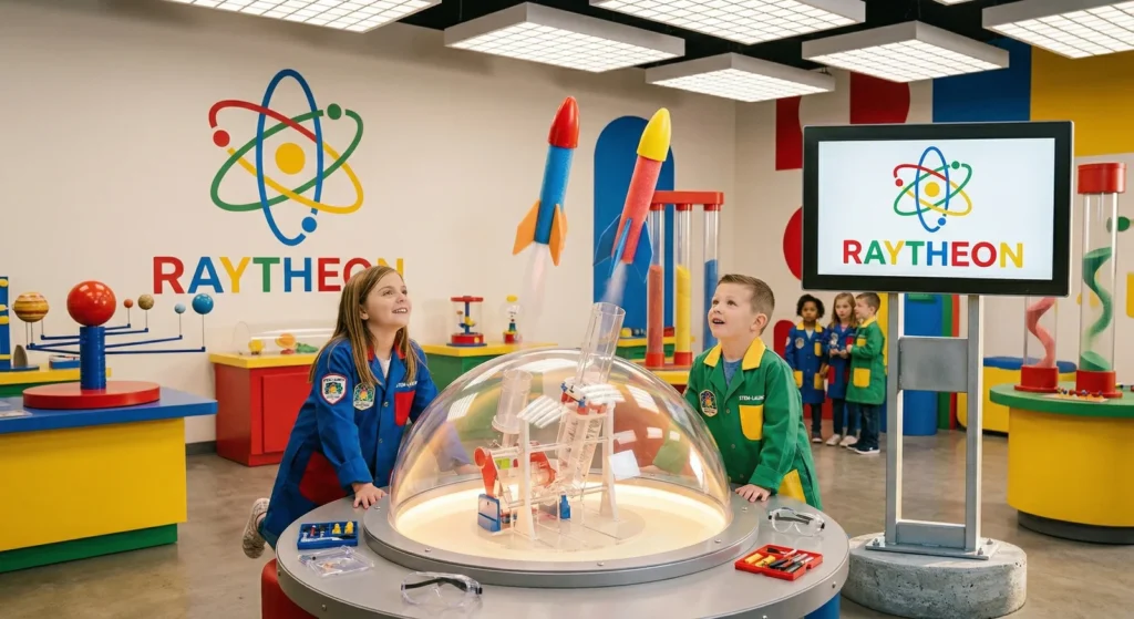
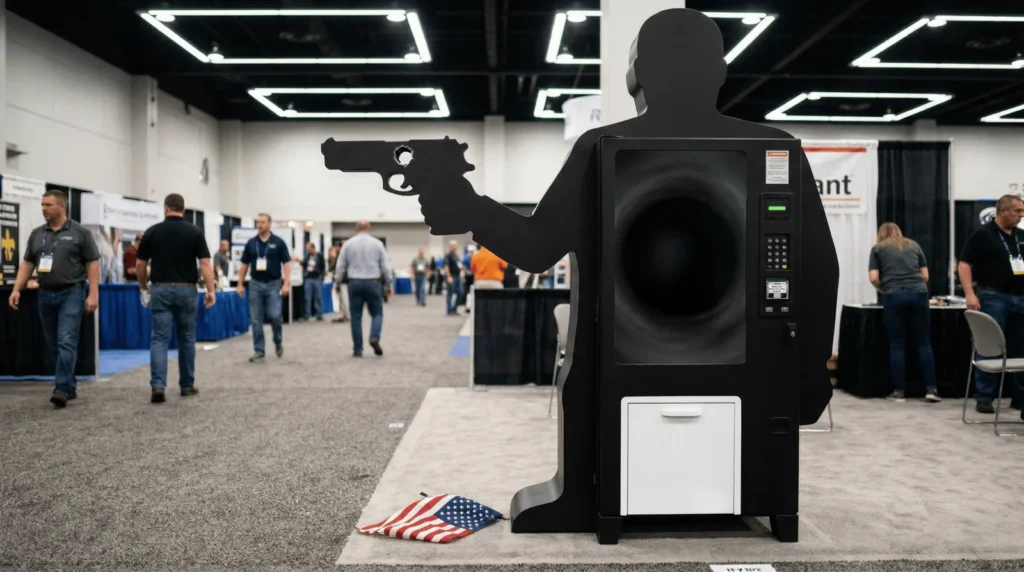

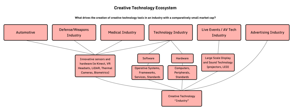
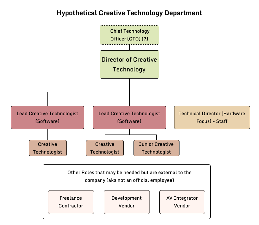
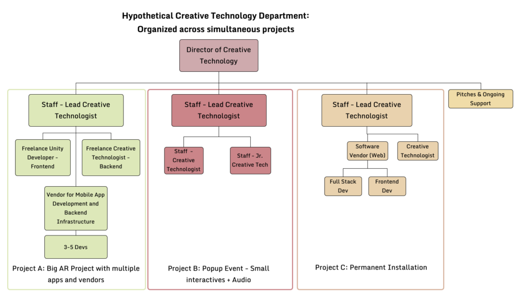
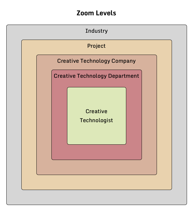
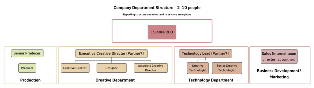
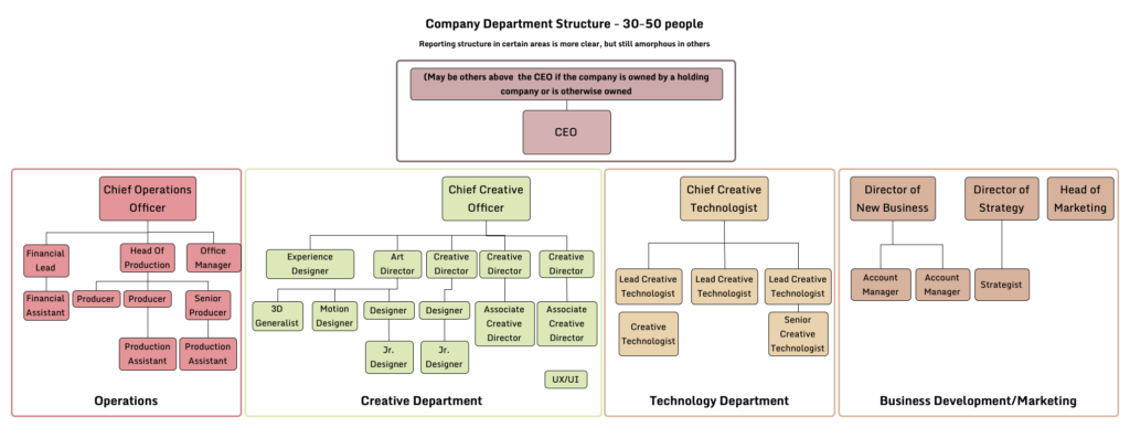
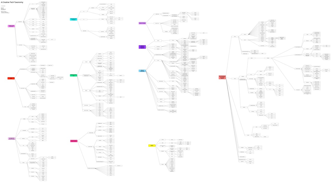
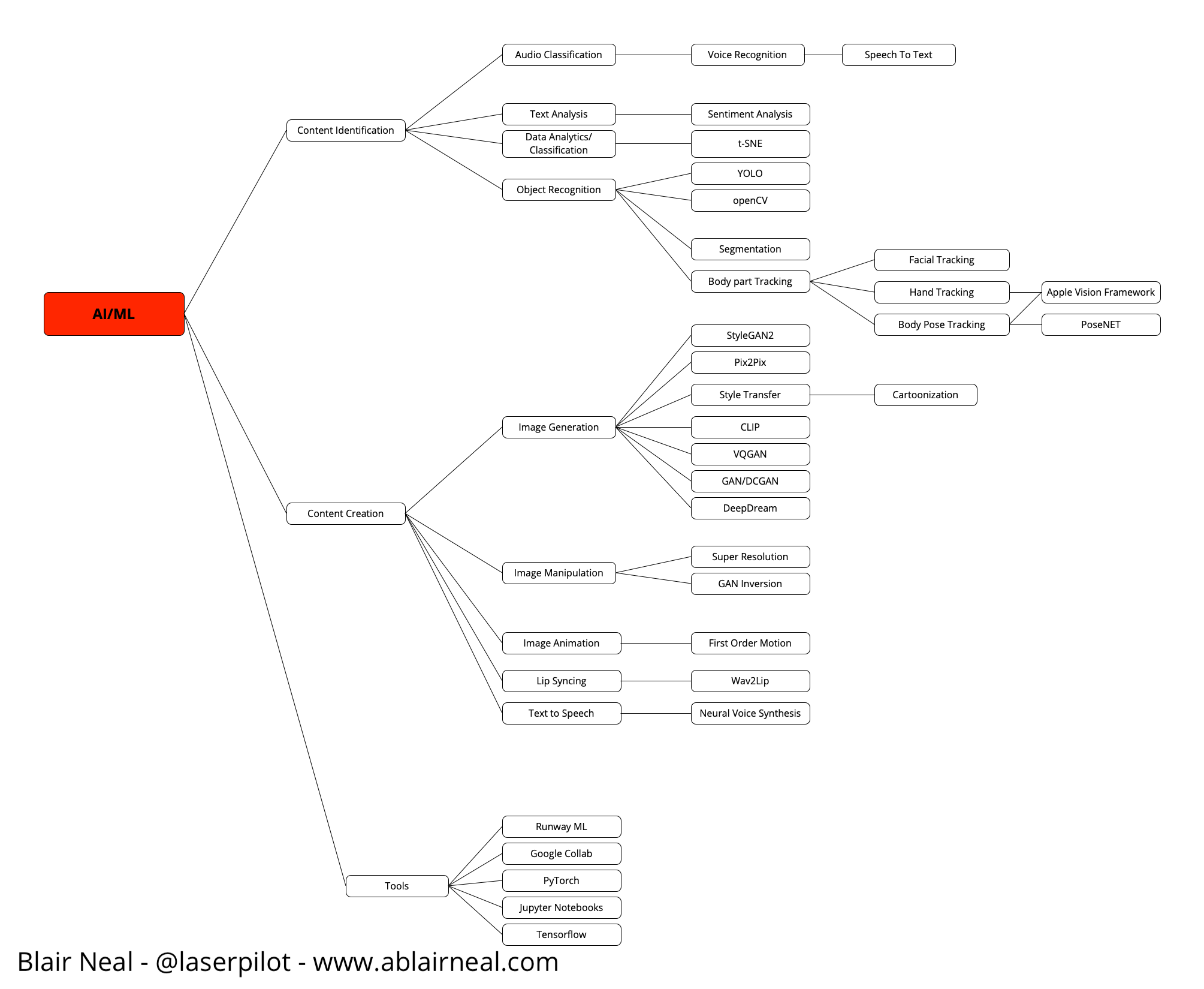
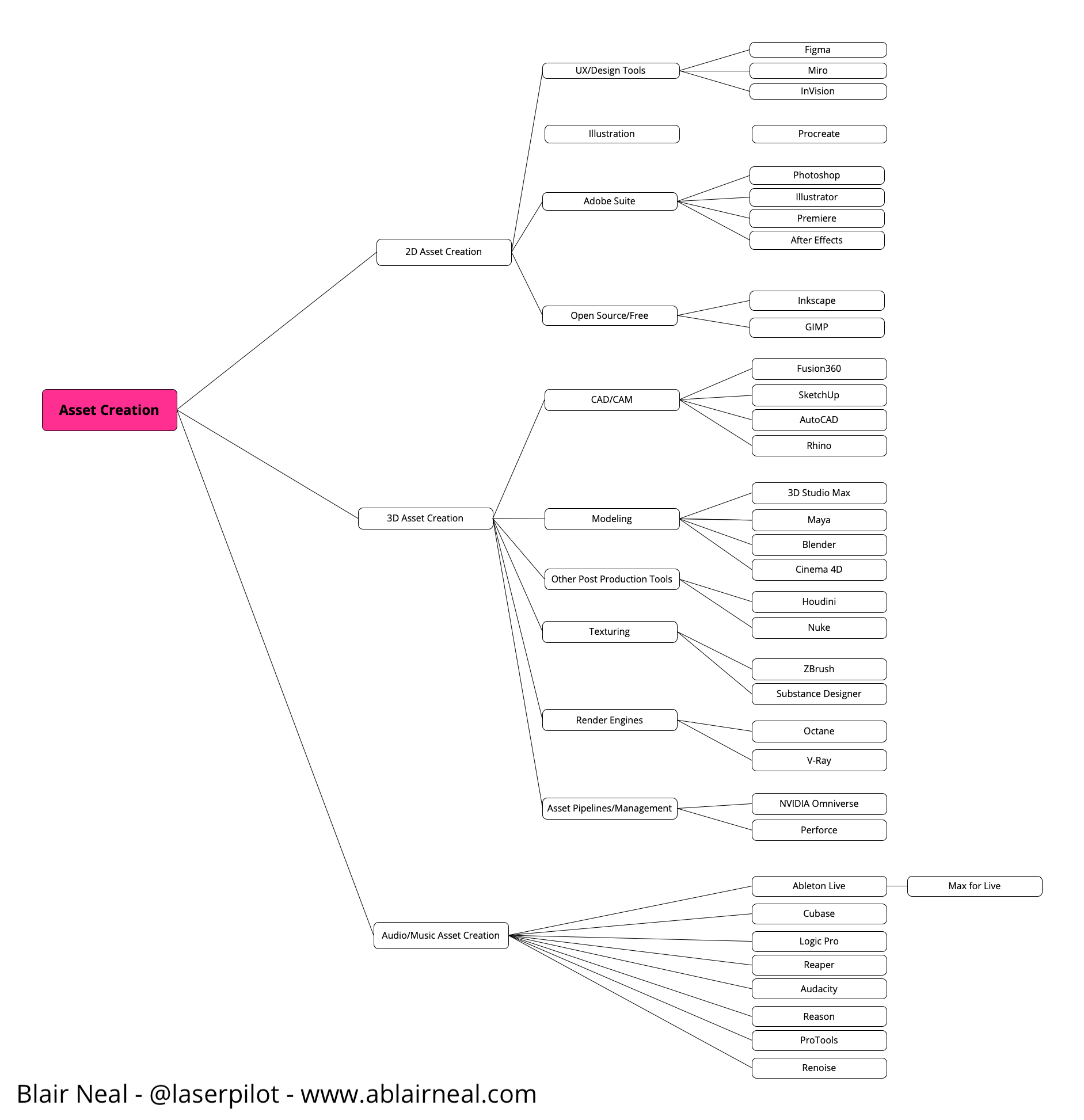


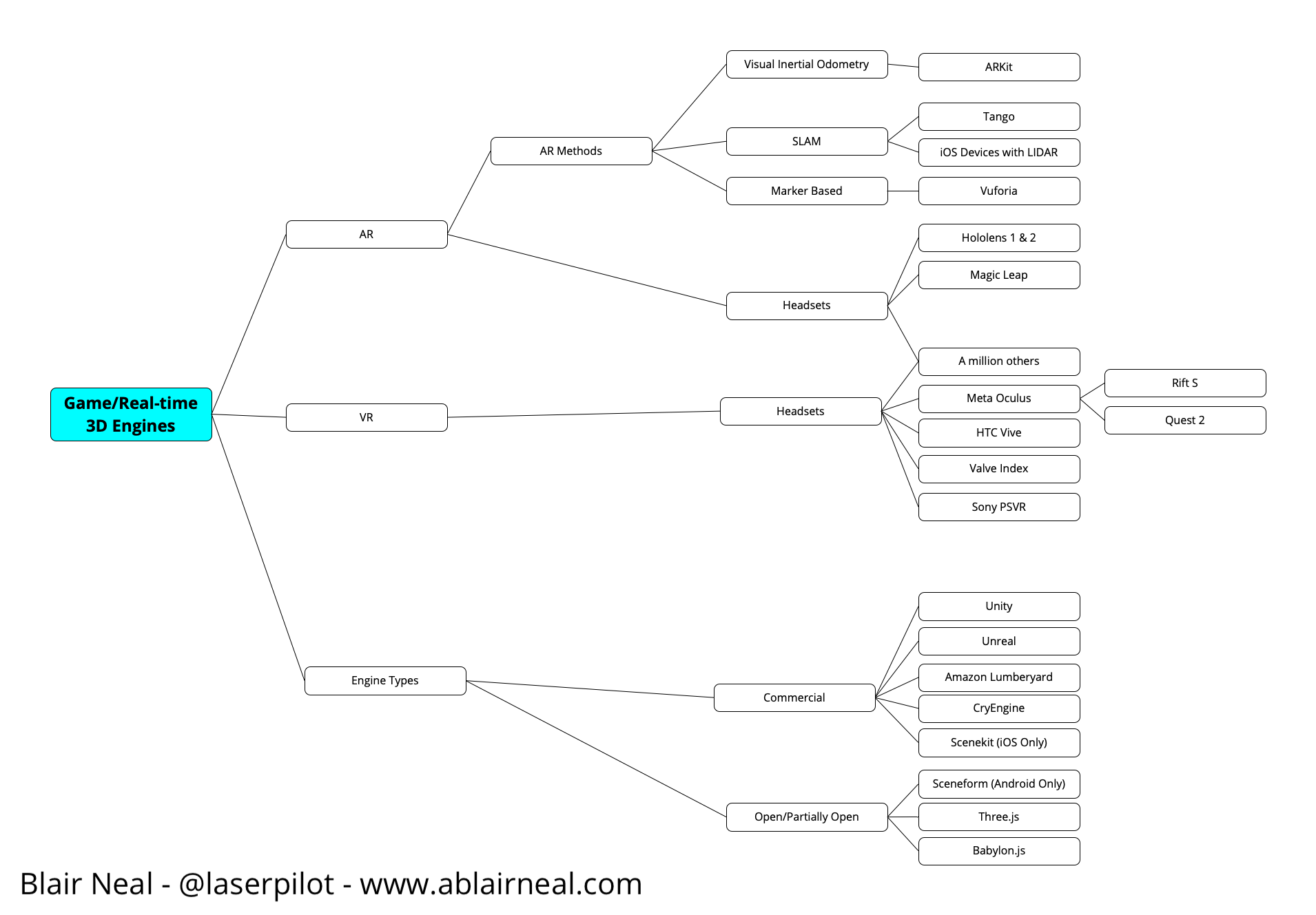
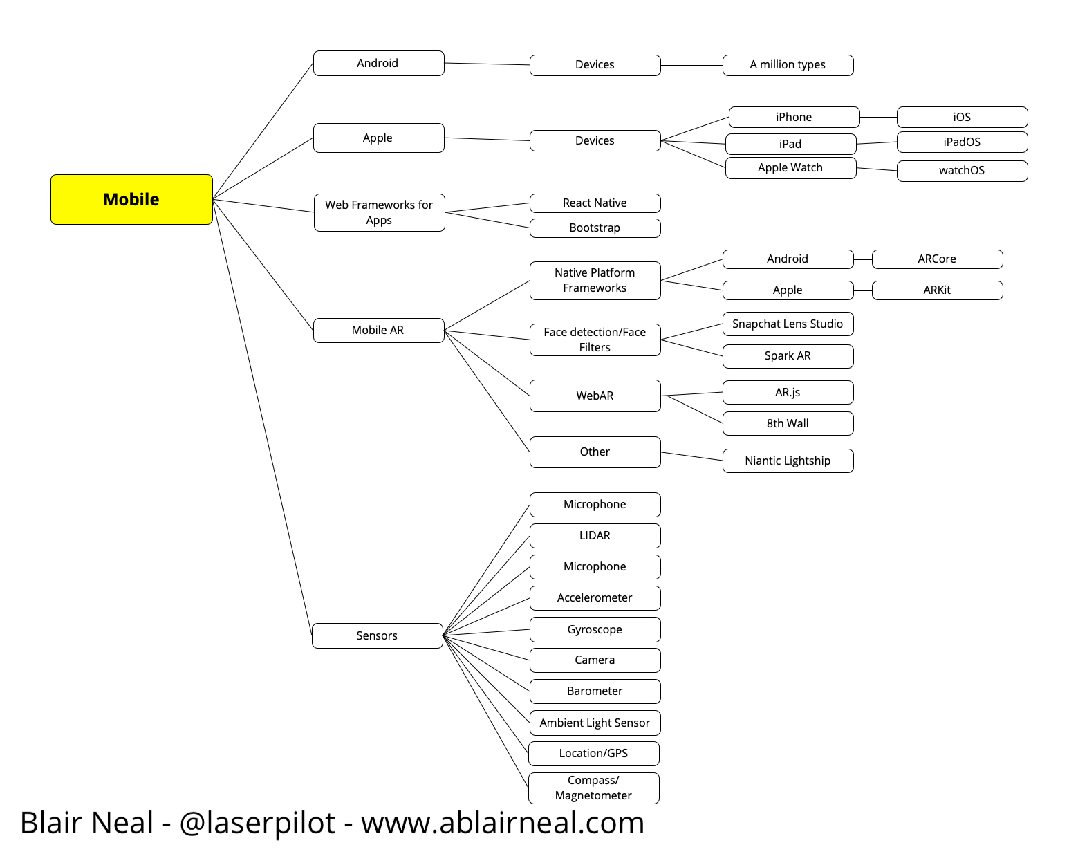
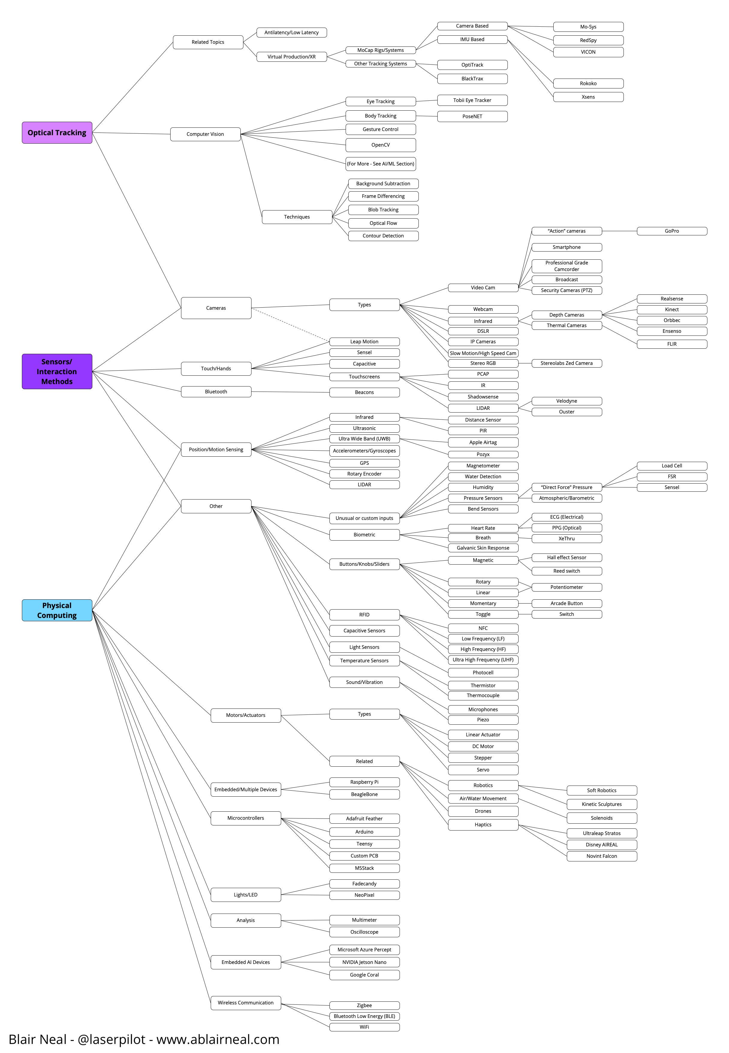
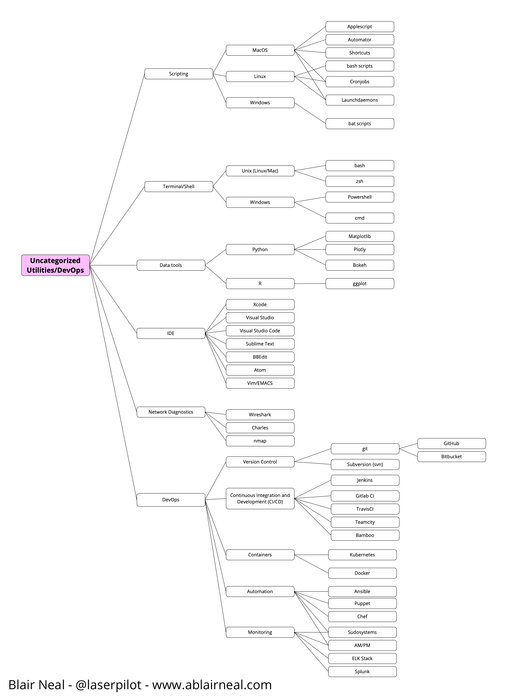
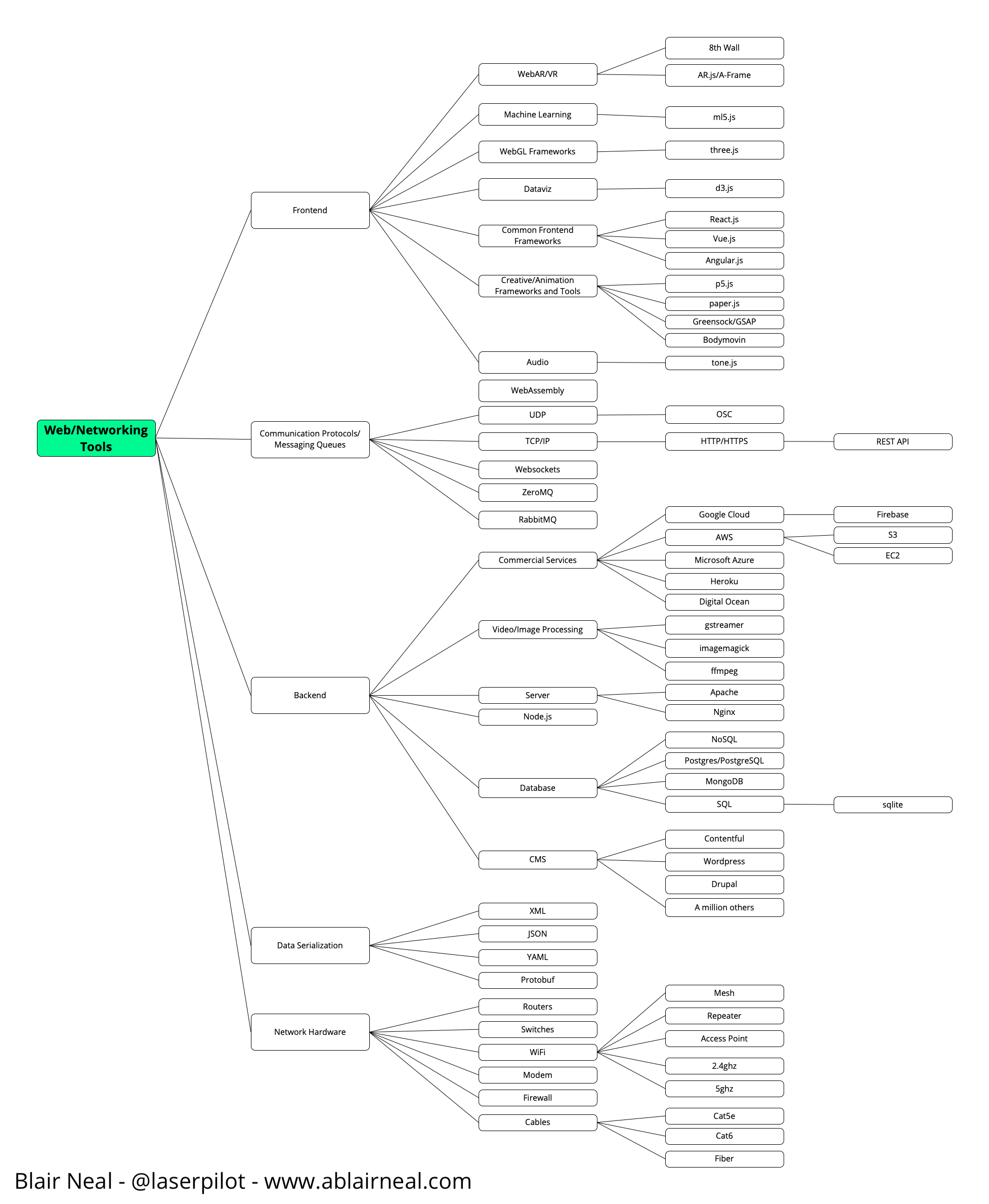
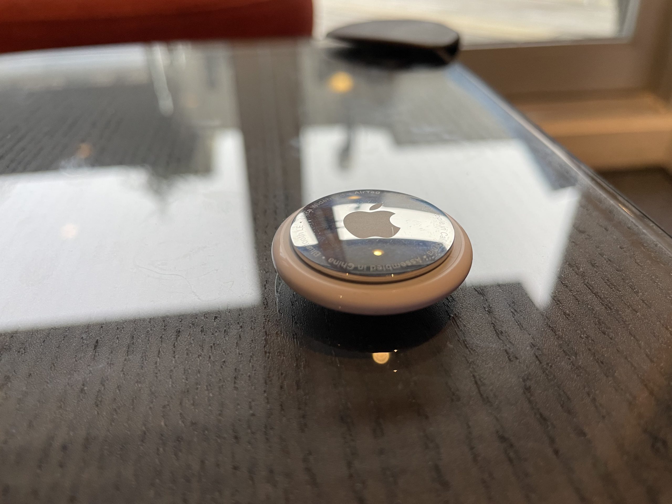
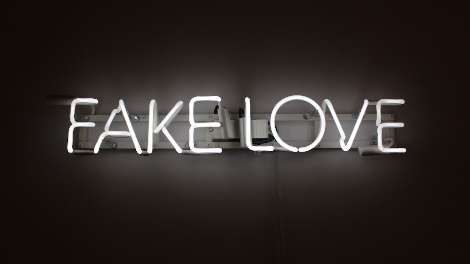
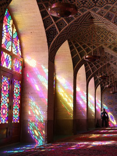
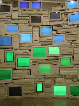

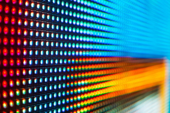
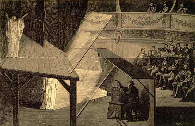
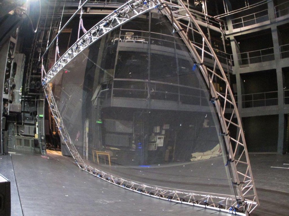
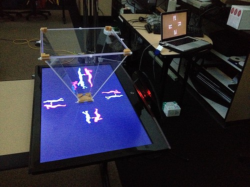
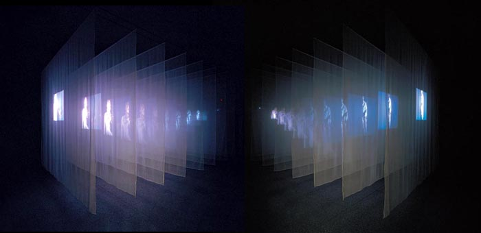
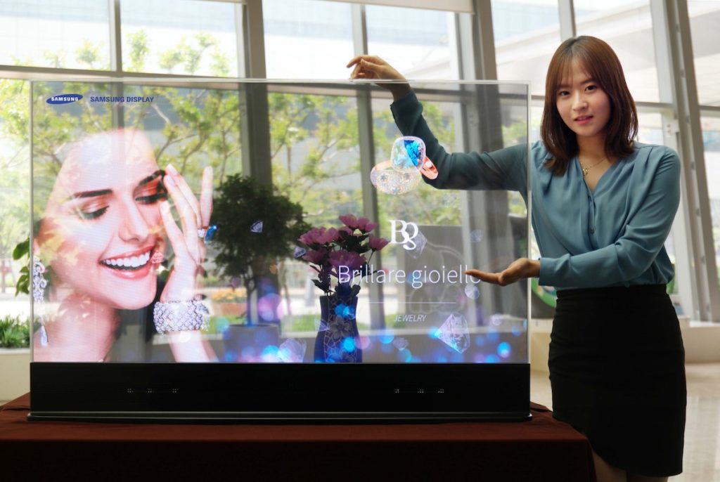
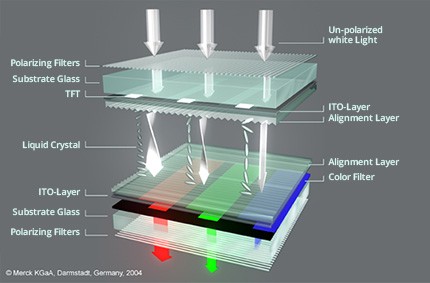
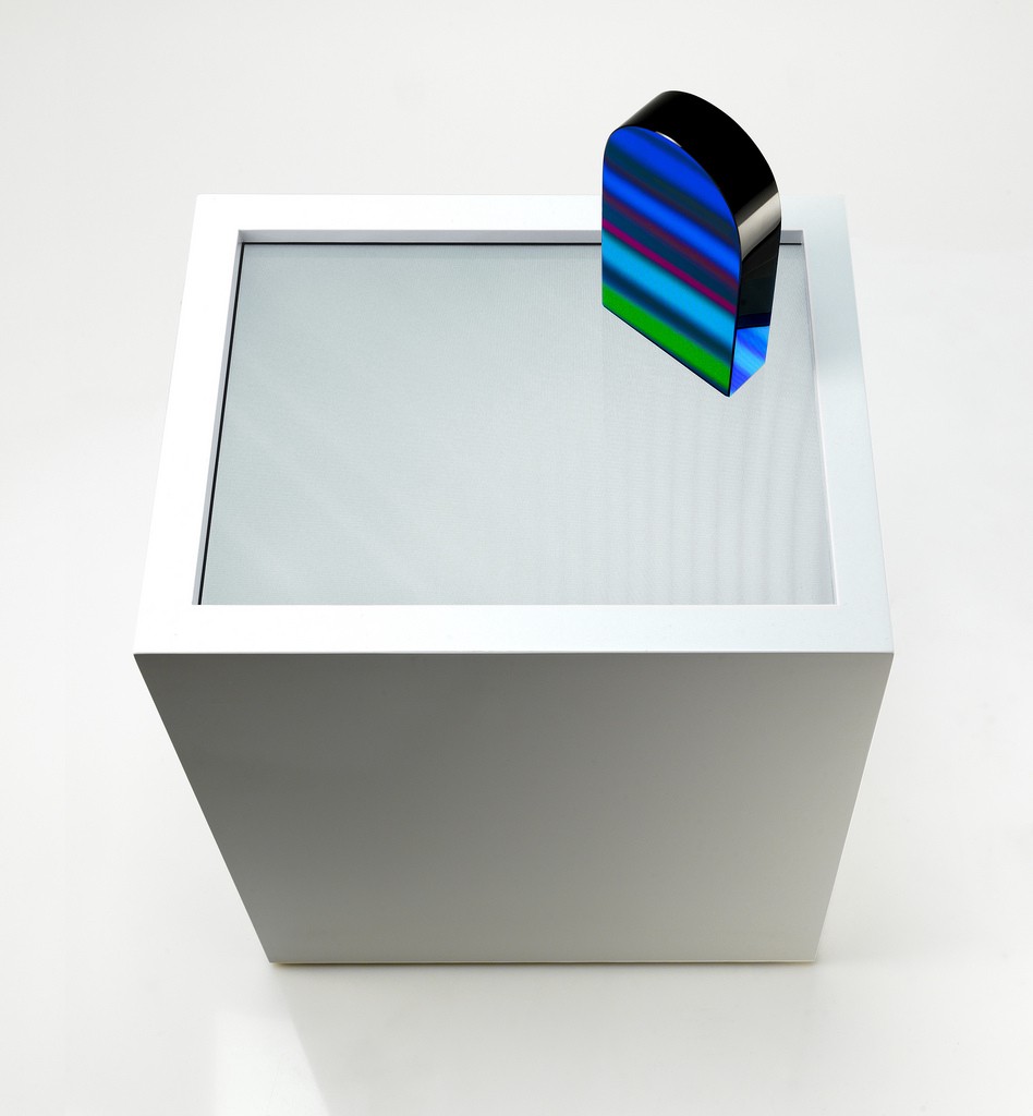
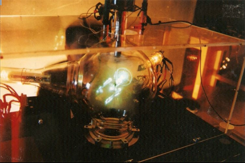
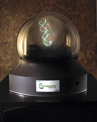
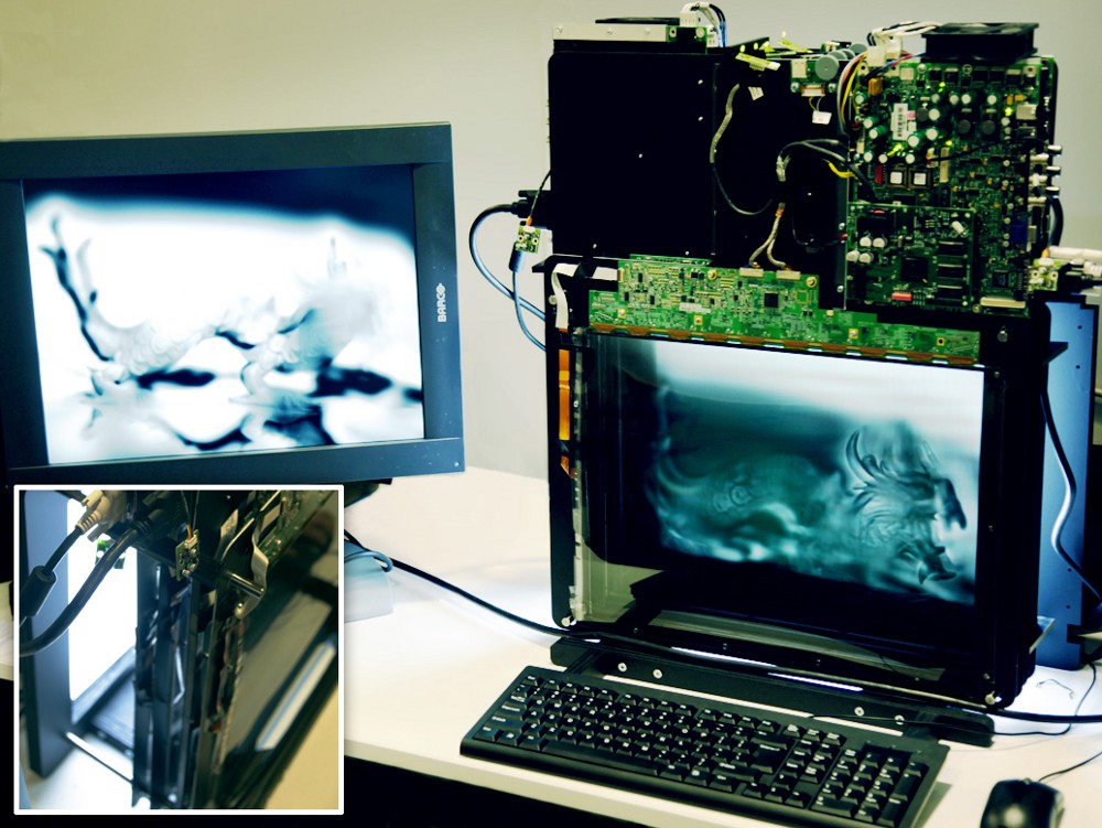
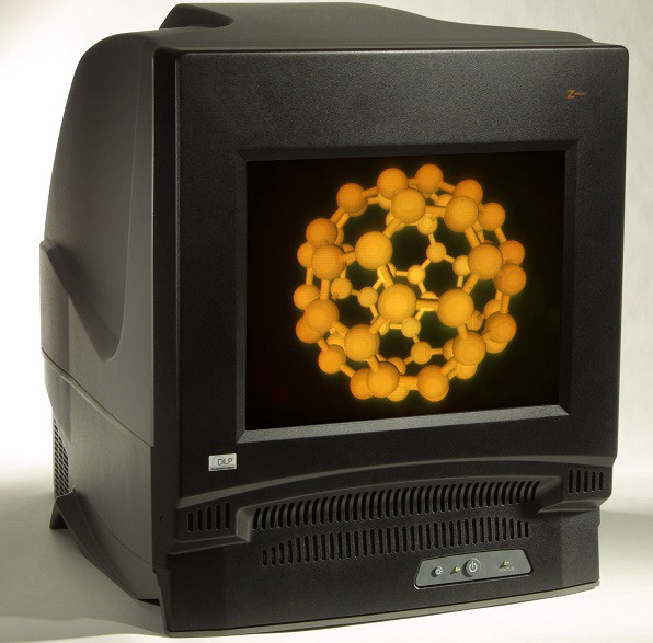
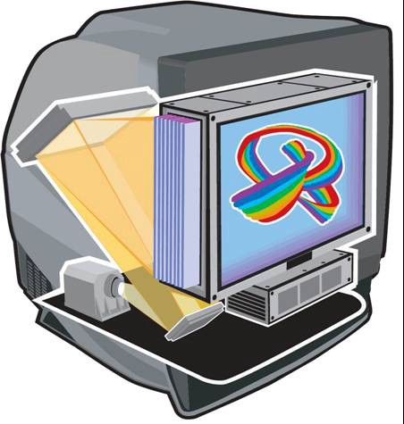
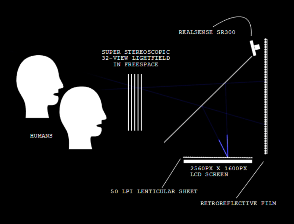
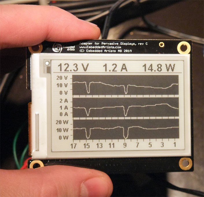
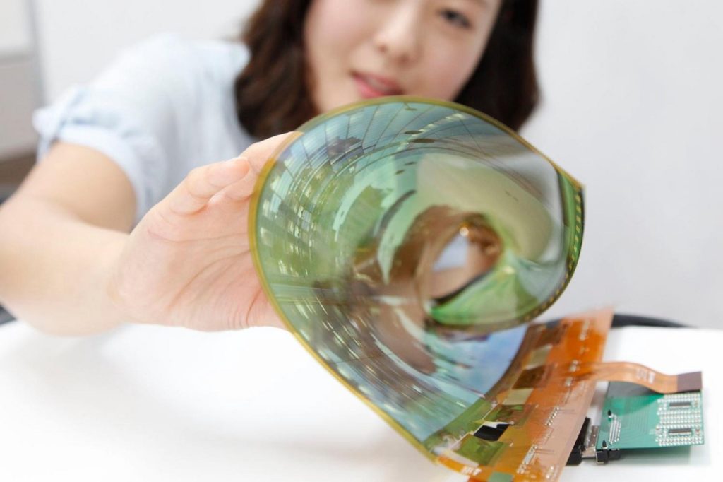
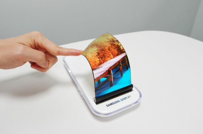
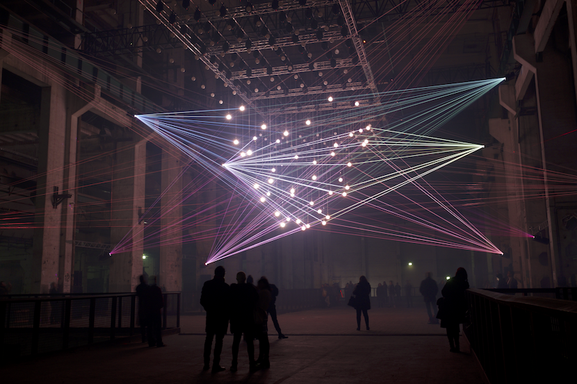
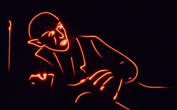
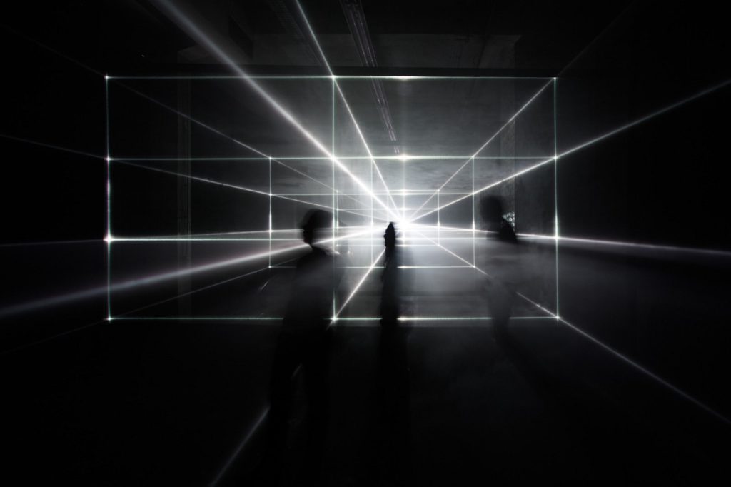
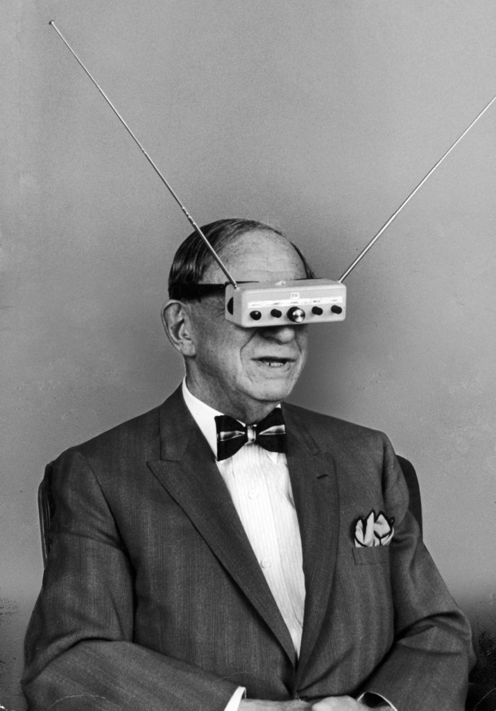
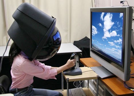
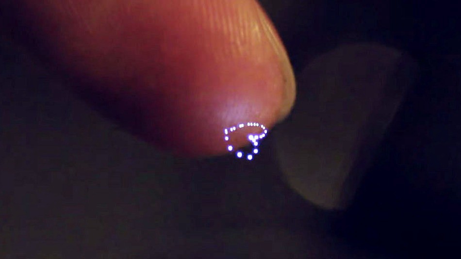
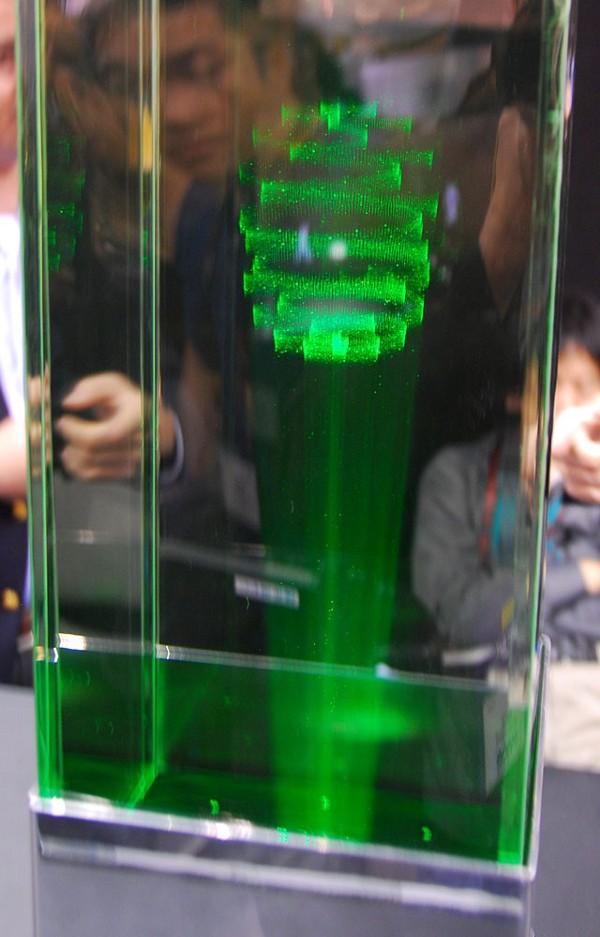
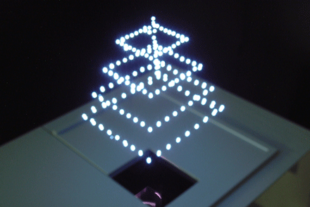
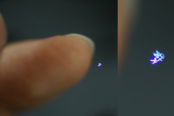
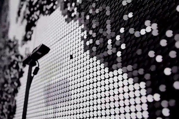

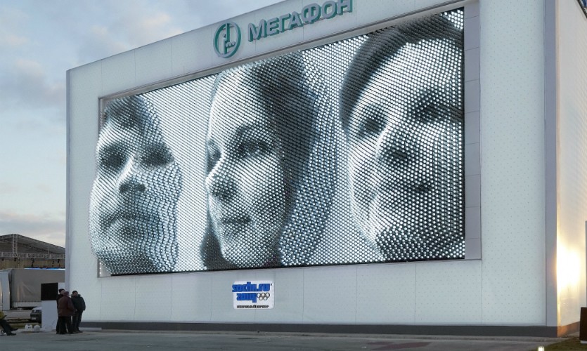
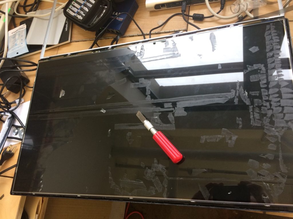